


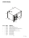
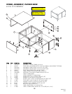
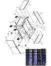
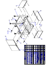
CLEVELAND RANGE OEB 6.20/10.10
SEQUENCE OF OPERATIONS
When using these instructions refer to the OEB 6.20/10.10 wiring schematic.
1 When incoming power (220 VAC) is connected to the combi, 220 VAC is sent to
a The contacts 2,4 and 6 of the Safety Contactor (KO)
b The terminals 2 and 3 of the Control Power Switch (S1)
2 When the Control Power Switch (S1) is turned on (closed)
a The red light on the switch is energized.
b Incoming power (220 VAC) is sent through the 2A fuse (F1.1) to
• The 12 vdc power supply (G1)
◊ 12vdc is sent to terminals 3 and 4 of the connector X10 on the Control
Board (A10)
• Terminal 1 of connector X12 on the Control Board (A10)
• Terminal 10 of connector X13 on the Control Board (A10)
• The return of the Supply is sent to terminal 7 of connector X13 on the Control
Board (A10)
c With 220 VAC to the Control Board (A10) The Operation Board (A11) is
energized
• An alarm will sound for one second
• All the LED’s and the display will energize one at a time.
• “STARTING” will be displayed for 3 seconds
• “please wait” will be displayed
• The international model number will be displayed
• The time and date will be displayed and this will continue until the on/off
switch is depressed.
3 When the ON/OFF is depressed with the combi in the steam mode
a After a date change (the first time the combi is turned on) the display will ask
“Generator Flush?”. If no answer is given in 10 seconds or a yes is indicated the
flush will begin.
• 220 VAC is sent from terminal 1 of connector X13 on the Control Board
(A10) to the Generator Pump (M4).
• As the water level drops below the probes the fill solenoid (Y3) will energize.
This rocking of the water will help flush scale from the generator.
• Then the pumps will be energized again
• When the condensate box is heated to 140 degrees F at the B3probe, 220 VAC
is sent from terminal 5 of connector X12 to the condenser valve (Y1) until the
temperature drops.,
b The display will show the set temperature and set time when the flush cycle is
complete.
c The Control Board (A10) will check the water level by looking for a ground at
terminals 1 and 2 on connector X15. These are connected to the high and low
probes (B1) in the steam generator.
61