


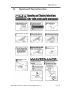

Getting Started
2.2. Receiving and Installation
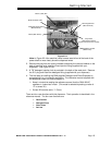
The dishwasher is shipped from the factory in a corrugated box on a wooden pallet. The
installation guidelines give a systematic procedure for setting up the machine.
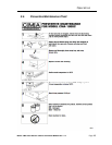
Start by removing the packaging material. Unwrap the machine and check for the following
component parts:
The Wash Tank Scrap Screen is shipped inside the wash cavity of the machine. This screen must
be in place during operation. It has been designed to perform two basic functions:
1. Strain water that is circulating through the spray arms and pump assembly.
2. A basket to catch broken glass, or heavy solids that may plug the impeller.
Set the machine in place, and level from side-to-side and front-to-back.
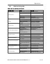
2.2.1. Electrical
1
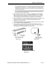
A 50-amp, single-phase 230 volt, 60 Hz dedicated circuit should be used to supply electrical
energy to the CMA-180UC dishwasher (see specification sheet page
2). This system requires
three power wires, which include a current carrying neutral. An additional fourth wire must be
provided for ground. CMA and local codes require the CMA-180UC to be hardwired using #8
AWG (90°C) copper wire (minimum). Approximately 4-feet of ¾” flexible conduit with power leads
(L-1, L-2, Neutral and Ground) extending out of the conduit are provided for easily connecting the
power at installation. The power connection must be located such that there is sufficient length of
the flexible conduit remaining to permit the machine to be moved for cleaning.
2.2.2. Plumbing
2
The machine is equipped with a ½” NPT connection located at the lower left-hand corner (facing
the back) of the machine. A 140°F water line should be plumbed to this point (see specification
sheet page
2). The water line used must be of sufficient length and flexibility to permit the
machine to be moved for cleaning.
The supply water to the CMA-180UC must be a minimum of 140°F at 24 PSI (Pounds per Square
Inch) with a 6 GPM (Gallons Per Minute) flow rate and 60 GPH (Gallons Per Hour) recovery rate.
The pipe supplying the water must be ½” minimum. The plumbing connection is located at the
back of the machine. (See specification sheet on page
2).
The CMA-180UC may be supplied with an optional drain pump for elevated drains. For floor
gravity drain applications the drain pump should not be used and a good commercial grade hose
needs to be connected to the discharge side of the diverter valve (drain valve) and run to the floor
drain. If removing a drain pump, safe-end (insulate electrically) the white and purple wires and
secure them out of the way. If a drain pump is used with a floor drain, the drain hose must rise 12
to 16” before dropping to the floor drain (to reduce any chance of the pump cavitations).
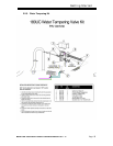
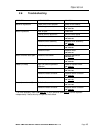
2.2.3. BETA Detergent And Rinse Dispenser (Optional)
Note: If you are installing the optional CMA Supplied Detergent and Rinse
Dispenser follow the instructions in Section
2.2.4 NOVA Detergent and Rinse
Dispenser
.
1. A mounting plate for ½” conduit is provided on the top right-hand corner (facing
the back) of the machine.
1,2
All electrical and plumbing connections must be made by a qualified person who will comply with
all available Federal, State, and Local Health, Electrical, Plumbing and Safety codes
MODEL CMA-180UC INSTALLATION & OPERATION MANUAL Rev. 1.13 Page
5