


Getting Started
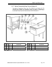
2.2.9. Field Installed Accessories
Installation of the accessory chemical pumps must be performed by qualified
personnel.
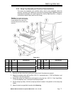
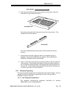
2.2.9.1. Chemical Dispensers
1. Checkvalves should be installed directly at the mixing chamber coupling.
There are two 1/8” FPT mounting holes provided, which will position the
checkvalves parallel to the machine avoiding any chemicals from dripping onto
the stainless steel should a leak develop. Simply remove the plug from the
mounting hole and install the checkvalve—be sure to use a proper sealing
compound or Teflon tape on the threads
*
.
NOTE: There are two mounting holes provided on the mixing chamber coupling,
one for rinse chemical and one for sanitizer chemical, but only one is
needed with the CMA-66H—for rinse chemical only.
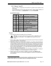
2. Connect only to the primary side of the Listed Class 2 Transformer, 208-230
VAC, 60 Hz, 100 VA maximum load.
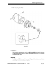
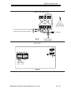
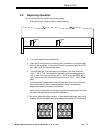
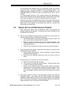
2.2.9.2. Hood Fan Motor
T1
T2
L1
L2
FAN CONTACTOR
TERMINAL BLOCK
WIRES FROM THE
POWER SOURCE *
WIRES TO THE FAN MOTOR
* 220 VAC OR 110 VAC
SUPPLIED BY ELECTRICIAN
DETERGENT SIGNAL
220 volts AC
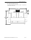
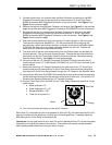
2.2.10. CMA-66 Heater
The 10kW heater located in the wash/final rinse tank has an independent power switch,
which needs to be activated when the machine is ready for operation.
As a safety precaution—if the wash tank is drained while the heater is left on, the thermostat
receives a signal to turn off the heater from a float switch located in the rinse end of the tank.
NOTE: The heater switch should always be turned off when the machine is not in operation.
*
*
Electrical and plumbing connections must be made by a qualified person who will comply with all
available Federal, State, and Local Health, Electrical, Plumbing and Safety codes
MODEL CMA-66 Installation & Operation Manual Rev. 1.06 01/11/05 Page
14