


Maintenance
4. Maintenance
The maintenance procedures detailed in this section are to be performed by qualified personnel.
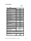
4.1. Timer assembly
The standard timer assembly consists of a (2 minutes per revolution) motor turning a common
shaft, which, in turn, rotates eight cams. As the cams rotate, they control various functions and the
sequence of the operational cycle.
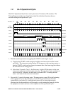
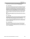
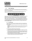
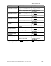
A label on the timer assembly identifies the individual function of each of the 8 cams. Cams 1
through 8 are positioned from left to right beginning with the “START” cam (cam 1).
HEATER
MOTOR
PAUSE
RINSESANI.FLUSHDRAINDET.START
Timer Assembly Label
Except for cams 1, and 3, all other cams can be user adjusted. The cam positions are all set at the
factory and only the cams controlling the chemical pumps (cams 2, 5 & 6) should ever need
adjusting. Each micro switch on the timer assembly is turned on and off by the cam its actuator
rides on. For all of the cams, except cams 1, 7 and 8, its corresponding switch is ON when its
actuator is down in the cam groove. (Cams 1, 7 and 8 are reverse acting and are turned ON when
the micro switch actuator is up out of the groove.) Opening the groove of any cam other than cams
1, 7 or 8 will increase the amount of time that the micro switch is held ON. The cams are slip-fit
and a cam adjustment wrench is provided (a small screw driver or the edge of a table knife can
also work to adjust the cams).
4.1.1. Cam Adjustment
The two sides of each cam connect to the shaft with a slip-fit so all cam adjustments are
made by rotating one side of the cam on the shaft to either increase or decrease the size
of the cam groove.
1. Turn off the circuit breaker providing power to the machine before accessing the timer
assembly.
Caution: One of the terminals on the main power switch remains “hot” even when the
machine’s main power switch is turned off—so turn the power off at the circuit
breaker.
2. Remove the two screws securing the front lower panel.
3. Using the timer assembly label, determine which cam is to be adjusted. Double check
by counting over from cam 1 to the cam to be adjusted.
4. Determine which edge of the cam groove to be adjusted is the leading edge (contacts
the limit switch actuator first when the shaft is rotating) and which edge of the groove
is the trailing edge. The leading edge of the cam groove determines when in the cycle
the control action begins and should not be changed.
5. Adjust the trailing edge of the cam groove by rotating the appropriate side of the cam
in the proper direction to either increase or decrease the cam’s groove; resulting in
increasing or decreasing the total time that switch will be held ON.
MODEL GL-X INSTALLATION & OPERATION MANUAL Rev. 1.00A –08/04/05
PAGE
10