


Getting Started
2.2. Receiving and Installation
The glasswasher is shipped from the factory in a corrugated box on a wooden pallet. The
installation guidelines give a systematic procedure for setting up the machine.
1. Start by removing the box and packaging material. Check for the following component parts:
A. Drain Screen:
The Wash Tank Scrap Screen is shipped inside the wash cavity of the machine. This
screen must be in place during operation. It has been designed to perform two basic
functions:
• Strain water that is circulating through the spray arms and pump assembly.
• A basket to catch heavy solids or broken glass that could plug the pump.
B. Spray Arms
The end caps on the spray arms have been caped to protect them in shipping. Remove
the cap from the spray arms.
C. Tube Stiffeners:
The tube stiffeners must be used to prevent the feed tubes from curling up inside the
chemical pail allowing the tip to rise out of the chemical. Remove the tie-wraps securing
the tube stiffeners to the dishmachine to free them up for use.
2. Set the machine in place and, using the leg adjusters, level from side-to-side and front-to-back
(VERY IMPORTANT).
2.2.1. Electrical
*
A 20-amp, 115 volt, 60 Hz dedicated circuit must be used to supply electrical power to the GL-X
machine (see specification sheet page 2). The power connection must be such that there is
sufficient length of flexible conduit to permit the machine to be moved for cleaning.
2.2.2. Plumbing
*
The machine is equipped with a gate valve with a ½” female NPT connection located at the lower
left-hand corner (facing the back) of the machine. A 140°F water line should be plumbed to this
point. The water line used must be of sufficient length and flexibility to permit the machine to be
moved for cleaning.
A 1” male NPT fitting is provided for the drain connection on the discharge port of the diverter
valve (lower, right-hand corner of machine). This fitting may be removed and user provided
hardware might be used if necessary to facilitate compliance with local plumbing codes. Code
requires that the drain discharge provide an air gap no less than 1” or two pipe diameters;
whichever is greater, above the flood level rim of an approved floor drain.
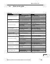
2.2.3. Post Instructions
Mount the wall chart provided where it can be easily viewed and instruct the operators on proper
cleaning and operation of the GL-X. The instruction chart is also provided as an appendix to this
manual (see appendix
1).
*
Electrical and plumbing connections must be made by a qualified person who will comply with all
available Federal, State, and Local Health, Electrical, Plumbing and Safety codes
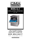
MODEL GL-X INSTALLATION & OPERATION MANUAL Rev. 1.00A –08/04/05 PAGE
6