


Page 13IQ–AMB-5 / IQ–SMX-6
Reference Manual
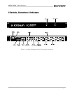
AMB-5 / SMX-6 IQ Mixer/Multiplexer
3
/16 in
(0.48 cm)
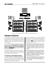
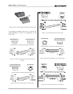
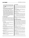
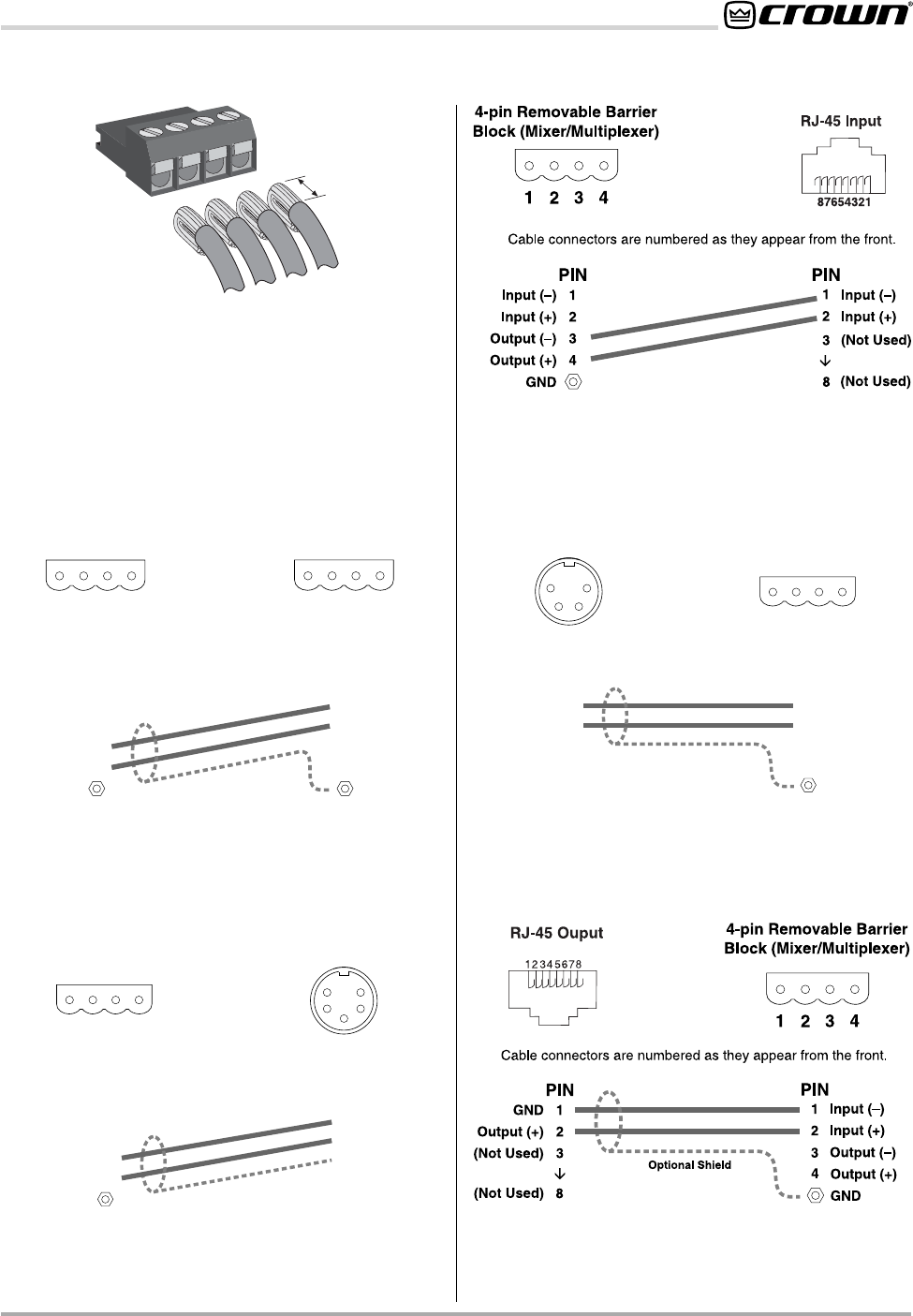
The following examples show how to connect the
mixer/multiplexer to other IQ components on the
Crown Bus:
PIN
1
2
3
4
PIN
1
2
3
4
Input (–)
Input (+)
Output (–)
Output (+)
Input (+)
Input (–)
Cable connectors are numbered as they appear from the front.
1
2
34
Mixer/Multiplexer 1
Output (–)
Output (+)
1
2
34
Mixer/Multiplexer 2
GNDGND
Optional Shield
PIN
1
2
Input (–)
Input (+)
4
1
3
2
5
5-pin DIN Input
Cable connectors are numbered as they appear from the front.
PIN
1
2
3
4
Input (–)
Input (+)
Output (–)
Output (+)
1
2
34
4-pin Removable Barrier
Block (Mixer/Multiplexer)
3
4
5
GND
(Not Used)
(Not Used)
GND
O
p
t
i
o
n
a
l
S
h
i
e
l
d
PIN
1
2
Output (–)
Cable connectors are numbered as they appear from the front.
PIN
1
2
3
4
GND
Output (+)
(Not Used)
(Not Used)
1
2
34
4-pin Removable Barrier
Block (Mixer/Multiplexer)
3
4
1
2
4-pin DIN Output
3
Input (–)
Input (+)
4
Output (+)
GND
Optional Shield
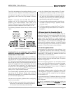
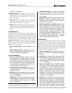
Figure 3.4 Four-Terminal Removable Barrier Block Plug
Figure 3.5 Crown Bus Wiring for Removable Barrier
Blocks
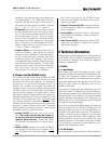
Figure 3.6 Crown Bus Wiring for 5-pin DIN Input
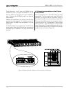
Figure 3.7 Crown Bus Wiring for RJ-45 Input
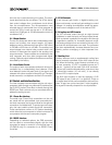
Figure 3.8 Crown Bus Wiring for 4-pin DIN Output
Figure 3.9 Crown Bus Wiring for RJ-45 Output