Page 26 IQ–AMB-5 / IQ–SMX-6
Reference Manual
AMB-5 / SMX-6 IQ Mixer/Multiplexer
+–+–+–+–
MAIN
AUDIO
OUT
2
AUDIO
OUT
1
BUS
STACK
IN
MAIN BUS
STACK
IN
3-pin output connector
+–+–+–+–
MAIN
AUDIO
OUT
2
AUDIO
OUT
1
BUS
STACK
IN
MAIN BUS
STACK
IN
2-conductor shielded cable
Phone (RCA) plug
First
Unit
Connect ground ( ) from
output to phone plug shield
Second
Unit
(–) No connection
SMX-6
SMX-6
SMX-6
SMX-6
PARALLELED
INPUTS
6 INPUTS
8
OUTPUTS
* When mixer inputs are paralleled, the total input impedance will drop by 1/
N where N is the number of inputs to be connected. Depending on the signal
source, this may place a limit on the number of possible outputs.
+–
AUDIO
IN
2
AUDIO
IN
1
LMP
0
-5
-10
-12
5
10
15
21
ADD 25
FOR MIC
LMP
0
-5
-10
-12
5
10
15
21
ADD 25
FOR MIC
0
+– +–
AUDIO
IN
2
AUDIO
IN
1
LMP
0
-5
-10
-12
5
10
15
21
ADD 25
FOR MIC
LMP
0
-5
-10
-12
5
10
15
21
ADD 25
FOR MIC
0
+
–
Do NOT tie ground terminals
of parallel inputs together
To signal
source
First
Unit
Second
Unit
2-conductor shielded cable
Connect shield to ground
terminal of input ONLY
No
phantom
power
SMX-6 SMX-6
SMX-6 SMX-6
SMX-6
SMX-6
SMX-6
SMX-6
MAIN
OUT
STACK
IN
PARALLELED
INPUTS
6x8
12 INPUTS
8
OUTPUTS
STACKED
OUTPUTS
6x8
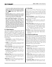
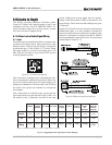
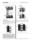
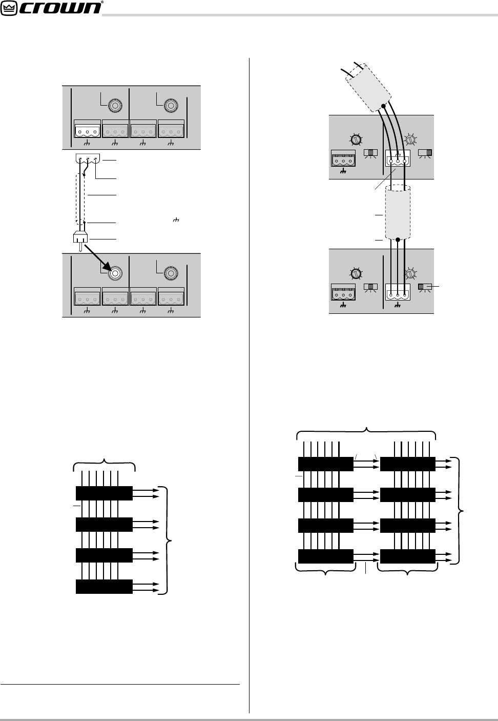
The correct way to wire stacked units is shown below:
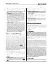
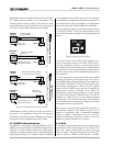
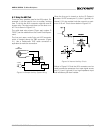
6.1.5 Paralleling inputs
When using more than one unit, the inputs may be
wired in parallel to increase the number of outputs that
a source can drive. This is shown in Figures 6.11-12.
For example, the audio signal in Figure 6.12 which
feeds Input 1 is available to the outputs of both units,
creating a 6x4 mixer.
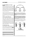
Important: If the source is a microphone which re-
quires phantom power (P), select it only at the first
input. Switch all other parallel inputs to mic (M).*
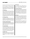
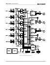
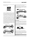
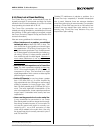
By using several units and a combination of parallel
inputs and stacked outputs, larger mixing configura-
tions (12x8, 24x4, etc.) can be created as shown be-
low:
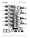
Figure 6.10 Stacking the Outputs of Multiple Units
Figure 6.11 A 6x8 Mixer Using 4 Mixer/Multiplexers
Figure 6.12 Paralleling the Inputs of Multiple Units
Figure 6.13 A 12x8 Mixer Using 8 Mixer/Multiplexers


