


Page 18
IQ Mixer/Multiplexer Hardware Installation
Rev. 0
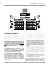
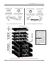
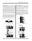
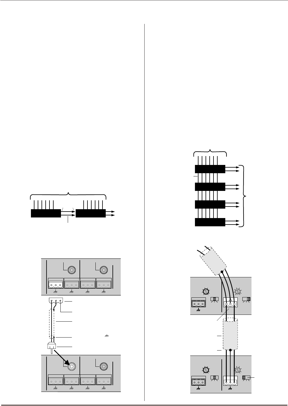
3.3.4 Stack Inputs
The stack in jacks (Figure 3.15) enable the audio
inputs to be increased by stacking 2, 3, or more
mixer/multiplexers to create a 12x2, 18x2 or wider
mixer. Use 2-conductor shielded cable to route the
signal from the main output of one unit to the stack
input (RCA phono jack) of the second unit. This is
shown in Figure 3.19. The stack input routes the
signal directly to the output of the second unit. Use
the outputs of the last unit
in the stack for connec-
tion to amplifiers or other external audio equipment.
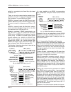
Note: The level of each signal on the stacked output
bus is controlled by the unit having the signal as an
input.
Stacking mixer/multiplexers can create an almost
unlimited number of inputs. However, there will still
only be two main and two auxiliary bus outputs for
connection to other equipment. See Section 3.3.5 to
find out how to increase the number of outputs.
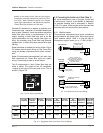
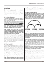
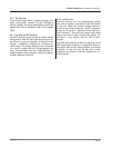
The correct way to wire stacked units is shown
below:
Fig. 3.19 Stacking the Outputs of Multiple Units
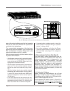
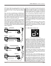
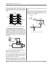
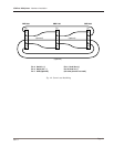
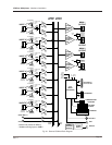
3.3.5 Paralleling Inputs
When using more than one unit, the inputs may be
wired in parallel to increase the number of outputs
that a source can drive. This is shown in Figures
3.20-21. For example, the audio signal in Figure 21
which feeds Input 1 is available to the outputs of
both units, creating a 6x4 mixer.
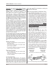
Important: If the source is a microphone which re-
quires phantom power (P) select it only at the first
input. Switch all other parallel inputs to mic (M).
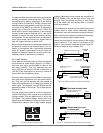
Note: When mixer inputs are paralleled, the total
input impedance will drop by
1
¦
N
where N is the
number of inputs to be connected. Depending on
the signal source, this may place a limit on the
number of possible outputs.
Fig. 3.20 A 6x8 Mixer Using 4 Mixer/Multiplexers
Fig. 3.21 Paralleling the Inputs of Multiple Units
Fig. 3.18 A 12x2 Mixer Using 2 Mixer/Multiplexers
SMX-6 SMX-6
MAIN
OUT
STACK
IN
12 INPUTS
2
OUTPUTS
STACKED
OUTPUTS
+–+–+–+–
MAIN
AUDIO
OUT
2
AUDIO
OUT
1
BUS
STACK
IN
MAIN BUS
STACK
IN
3-pin output connector
+–+–+–+–
MAIN
AUDIO
OUT
2
AUDIO
OUT
1
BUS
STACK
IN
MAIN BUS
STACK
IN
2-conductor shielded cable
Phone (RCA) plug
First
Unit
Connect ground ( ) from
output to phone plug shield
Second
Unit
(–) No connection
+–
AUDIO
IN
2
AUDIO
IN
1
LMP
0
-5
-10
-12
5
10
15
21
ADD 25
FOR MIC
LMP
0
-5
-10
-12
5
10
15
21
ADD 25
FOR MIC
0
+– +–
AUDIO
IN
2
AUDIO
IN
1
LMP
0
-5
-10
-12
5
10
15
21
ADD 25
FOR MIC
LMP
0
-5
-10
-12
5
10
15
21
ADD 25
FOR MIC
0
+
–
Do NOT tie ground terminals
of parallel inputs together
To signal
source
First
Unit
Second
Unit
2-conductor shielded cable
Connect shield to ground
terminal of input ONLY
No
phantom
power
SMX-6
MPX-6
MPX-6
MPX-6
PARALLELED
INPUTS
6 INPUTS
8
OUTPUTS