Impinger I – 1450 Series Service Manual - Domestic 9
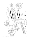
THERMOSTAT, COOLING FAN - REPLACEMENT
1. Shut off power at main breaker.
2. Remove control panel top and front cover.
3. Remove lead wires and mark for reassembly.
4. Remove two (2) screws and remove thermostat.
5. Reassemble in reverse order.
BURNER BLOWER MOTOR - REPLACEMENT
1. Shut off power at main breaker.
2. Remove control panel top and front cover.
3. Unplug motor connector.
4. Remove three (3) screws from blower tube at burner housing.
5. Remove air shutter assembly from old motor for installation on new motor assembly.
6. Reassemble in reverse order and check system operation.
NOTE: Check air shutter adjustment and adjust if necessary. Set air shutter at approx. 1/4" and adjust
to get a blue flame with an occasional tip of yellow under high flame. A view port in the burner assembly
should be used to observe flame.
BLOWER WHEEL, BURNER
This is part of the burner blower motor assembly.
TO REMOVE THE BLOWER WHEEL FOR PERIODIC CLEANING:
1. Shut off power at main breaker.
2. Remove control panel top and front cover.
3. Remove air shutter held by 3 screws.
4. Loosen set screws on blower wheel hub and pull straight out.
5. Reassemble in reverse order.
NOTE: There is no critical placement of the blower wheel on the motor shaft. Just back as far as
it will go and then spin the blower to be sure it is not rubbing.
BURNER CONTROL - REPLACEMENT
1. Shut off power at main breaker.
2. Remove control panel top and front cover.
3. Remove wires from control, note wire numbers and location for reassembly.
4. Remove Two (2) screws from control and replace.
5. Reassemble in reverse order and check system operation.
BURNER ASSEMBLY
1. Shut off power at main breaker.
2. Shut off gas supply.
3. Remove control panel top and front panel.
4. Remove gas control valve (See "GAS CONTROL VALVE")
5. Disconnect pilot tube.
6. Remove solenoid valve. (See "TEMPERATURE REGULATION VALVE")
7. Remove four (4) screws that secure the burner backing plate.
8. Remove burner assembly from housing, the main and pilot orifice, flame target, pilot shield (main and
extension), burner ignitor can now be changed or serviced as needed.
9. Reassemble in reverse order. Check all gas line fittings for leaks.
GAS CONTROL VALVE - REPLACEMENT
1. Shut off power at main breaker.
2. Shut off gas supply.
3. Remove control panel top and front cover.
4. Disconnect the gas piping from the back of the unit.
5. Remove the four(4) screws from the incoming nipple mounting bracket.


