


All specications subject to change without notice.
Phone: (800) 793-0093www.dacor.com
PLANNING
GUIDE
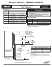
Note 2
B
A
Non-combustible
surface along
back wall
recommended
Top of
finished
counter
13” (33.0 cm)
max.
4
18” (45.7 cm)
min.
4
C
Suggested
location of
utilities
3
Note 5
Note 1
DR30ES, DR30EFS, DR30EIS, DR30EIFS
Distinctive
30” Wide
Electric Ranges
Document # PG05-008
Revised 11/09/12 Page 2/4
All tolerances +1/16” (+1.6 mm), -0 unless otherwise noted.
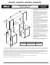
A* B
C
30 1/16” min.
(76.4 cm)
36” (91.4 cm) recommended
30” (76.2 cm) min.
37” (94.0 cm)
max.
FREESTANDING INSTALLATION CABINET CUTOUT DIMENSIONS - MODELS DR30ES, DR30EFS, DR30EIS AND DR30EIFS
* See the cutout dimensions on following page for self-rimming installations.
■ Failure to meet or exceed the maximum and
minimum dimensions/clearances stated may result
in a fire hazard.
■ The shaded area shown denotes the location of
the electrical junction box/receptacle. This is the
suggested location. For replacement purposes, the
location of the existing electrical supply may be
utilized provided that it does not interfere with the
sides or rear of the range.
■ Access to the remote circuit breaker panel/fuse box,
with the range in place and operating, must also be
allowed for in the installation.
■ The electrical junction box/receptacle must be
located so that it does not interfere with the range
when it is installed and under operation. In addition,
the junction box/receptacle must be located so
the range can be removed for service and remain
connected to power.
■ To eliminate the risk of burns or fire by reaching
over heated surface units, cabinet storage space
located above surface units should be avoided. If
cabinet storage space is to be provided directly
above the range, the risk of personal injury may be
reduced by installing a range hood.
■ In all instances, installation of a range hood is highly
recommended. The hood should project horizontally
a minimum of five (5) inches beyond the face of
the cabinets. See the range hood specifications for
minimum clearances.
■ The range may be installed flush to the rear wall.
See diagram and notes for rear wall surface
requirements. It is not necessary to install non-
combustible materials behind the range below the
countertop height.
■ Any openings in the wall behind the appliance or in
the floor underneath it must be sealed.
1
30” (76.2 cm) min. vertical clearance from top of range grates to bottom of uncovered wood or metal cabinet. 24” (61 cm) min. clearance if bottom of wood
or metal cabinets are protected by not less than 1/4“ (0.6 cm) flame retardant millboard covered with no less than No. 28 MSG sheet steel 0.015” (0.04
cm) stainless steel, or 0.024” (0.06 cm) aluminum or 0.020” (0.05cm) copper. 30” (76.2 cm) min. clearance between top of range grates and bottom of
unprotected wood or metal cabinet. If installing range hood, check the hood specifications for minimum required clearances.
2
Cabinet/countertop depth is at discretion of customer but cabinet face SHALL NOT protrude further than rear of front panel. See Product Dimensions.
3
Consult local code and following pages for requirements.
4
This specification not applicable for cabinets more than a horizontal distance of 10” (25.4 cm) from edge of range.
5
10” (25.4 cm) min. to combustible sidewalls above range (both sides).