


5
in s T a l l a T i o n sp e C i f i C a T i o n s
Verify that all required components have been provided. If
any item is missing or damaged, please contact your dealer
immediately. Do not install a damaged or incomplete appliance.
• Mounting Screws
• Use and Care Videotape
• Oven Racks
• Broiler Grill and Pan
• Exhaust Grill/Lower Trim
• Rear Top Trim
• GlideRack™ Oven Rack
• Light Lens Pry Stick
A qualified technician must complete the installation of this built-in
appliance. Proper installation is your responsibility.
Carefully check the location where the oven is to be installed. The
oven should be placed for convenient access. Make certain that
electrical power can be provided in the selected location.
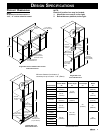
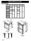
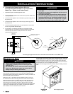
Plan the installation so that all minimum clearances are met or
exceeded. Dimensions shown provide minimum clearances,
unless otherwise noted. Be certain that proper clearance is
provided for the oven door when it is in the open position.
The specified minimum cabinet depth and width must be provided.
The cabinet depth and width must completely enclose the
recessed portion of the oven.
Cabinet cutout dimensions must be used as indicated. All contact
surfaces between the appliance and the cabinet must be solid and
level. The oven support platform must be flush with the bottom
edge of the cabinet cutout.
Make certain that you have everything necessary to ensure a
proper installation before proceeding.
ve R i f y i n g T h e pa C k a g e Co n T e n T s
in s T a l l a T i o n pl a n n i n g
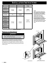
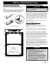
Provide a platform within the cabinet upon which the oven will be
supported. The platform must be installed level and straight. The
top edge of the platform must be flush with the cutout at the front
of the cabinet. There are no provisions to level the oven after it
has been installed. 3/4” (19mm) thick plywood is recommended.
NOTE:
An oven that is not level may provide poor or inconsistent
baking results.
in s T a l l i n g T h e su p p o R T pl a T f o R m i n
T h e C a b i n e T
WARNING
WARNING – If the electrical service provided does not
meet the product specifications, do not proceed with
the installation. Call a licensed electrician to correct.
It is the owner’s responsibility to ensure that a qualified electrician
performs the electrical connection of this appliance. The electrical
installation, including minimum supply wire size, must comply with
the National Electric Code ANSI/NFPA 70-1990* (or to the latest
revision) and local codes and ordinances.
*A copy of this standard may be obtained from:
National Fire Protection Association
1 Batterymarch Park
Quincy, Massachusetts 02269-9101
The correct voltage, frequency, and amperage must be supplied
to the appliance from a separate, grounded, single phase circuit
that is protected by a properly sized circuit breaker or time-delay
fuse. If a time-delay fuse is utilized, fuse both sides of the line (L1
and L2).
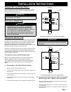
The required voltage, frequency and amperage ratings are listed
on the product data plate (located inside the intake grill to the left
of the door latch) and in the Table below.
The correct voltage, frequency, and amperage must be supplied
to the appliance from a separate, grounded, single phase circuit
that is protected by a properly sized circuit breaker or time-delay
fuse. If a time-delay fuse is utilized, fuse both sides of the line (L1
and L2).
The required voltage, frequency and amperage ratings are listed
on the product name plate (located inside the intake grill to the left
of the door latch) and in the Table below.
NOTES:
1. Preheat times and cavity temperature recovery
times will be increased slightly if operating on a
120/208 volt power supply.
2. 208V models should not be connected to 240V
source power.
3. Power supply must be an isolated circuit.
el e C T R i C a l po w e R su p p l y
Re q u i R e m e n T s