


4
In s t a l l a t I o n pl a n n I n g
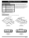
Installation Requirements
WARNING
To reduce the risk of fire, plan the installation so that
all minimum required clearances are met or exceeded.
Dimensions provided are minimum clearances, unless
otherwise noted.
An Integrated Ventilation System (IVS) installed in •
a custom hood canopy constructed of combustible
materials must be installed with the combustible
material structure a minimum of 36” (914mm) above
the appliance cooking surface.
An IVS installed in a custom hood canopy that is •
constructed of non-combustible materials must be
installed with the non-combustible material structure a
minimum of 30” (762mm) above the appliance cooking
surface.
An IVS installed in a custom hood canopy that is •
constructed with a Dacor IHL series stainless steel
hood liner must be installed with the non-combustible
material structure a minimum of 30” (762mm) above
the appliance cooking surface.
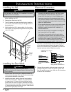
The IVS must be mounted so that it can be removed if •
service is required. Make sure that the material around
the edge of the cutout, behind the IVS mounting holes,
is strong enough to hold the weight of the unit.
Electrical Requirements
WARNING
To Reduce the Risk of Fire And Electric Shock:
The electric service to the IVS must be installed only •
by a licensed electrician.
When installing models IVS1 and IVS2, install the •
unit only in conjunction in-line blower or remote
blower models specified in these instructions. The
maximum current rating for the blower must not
exceed 7 Amps.
It is the owner’s responsibility to ensure that the electrical
connection of this appliance is performed by a qualified
electrician. The electrical installation, including minimum
supply wire size and grounding, must be in accordance with
the National Electric code ANSI/NFPA* (or latest revision)
and local codes and ordinances.
*A copy of this standard may be obtained from:
National Fire Protection Association
1 Batterymarch Park
Quincy, Massachusetts 02269-9101
The ground wire on this appliance must be connected •
to a grounded, metallic, permanent wiring system or
grounding conductor installed by a licensed electrician.
Do not ground the appliance or appliance wiring to a •
gas pipeline or to the neutral (white) power supply wire.
Do not install a fuse in the neutral or ground circuit. •
Connect the IVS directly to an electrical junction box.•
The IVS needs to be hard wired, according to local •
code, directly to a dedicated three wire grounded,
single phase circuit rated at 120 Vac 60 Hz, 15 Amps.
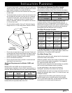
Planning the Duct Work
WARNING
To reduce the risk of fire and to properly exhaust •
air, be sure to duct air outside the house or building.
Do not vent exhaust air into spaces within walls or
ceilings or into attics, crawl spaces or garages.
To prevent combustion by-products, smoke or odors •
from entering the home and to improve efficiency,
tape all duct joints securely.
Use only duct work deemed acceptable by state, •
municipal and local codes.
Range hoods may interrupt the proper flow of •
smoke and combustion gases from furnaces, gas
water heaters and fireplaces. To avoid drawing
lethal gases into the home, follow the manufactures
recommendation for these devices and consult NFPA
and ASHRAE recommendations.
When installing models IVS1 and IVS2, DO NOT •
install an additional in-line or external blower to
increase the length of the duct run. Even small
differences between blower air flow rates can greatly
reduce the air draw by the hood.
When installing models IVSR1 and IVSR2, DO •
NOT install more than one in-line or external blower
to increase the length of the duct run. Even small
differences between blower air flow rates can greatly
reduce the air draw by the hood. Install only the
in-line or remote blower models specified in these
instructions.
Duct System Design Requirements
All duct work materials (including screws and duct tape) •
must be purchased separately by the customer.
Ducts must be of adequate size and duct runs should •
be as short and straight as possible. Where turns are
necessary, keep the turning radius as large and smooth
as possible.