


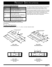

6
Electrical Connection
WARNING
To avoid electric shock or fire hazard, prior to •
connecting the electrical wiring to the hood, make
sure that power to the IVS power supply line is
turned off at the fuse box or circuit breaker panel.
Improper connection of the hood electrical wiring •
may create an electric shock or fire hazard and may
result in damage to the hoods electrical system. See
page 6 for specifications.
Do not ground the hood to the neutral (white) power •
supply wire. Connect the hood ground wire to a
separate, properly grounded wire installed by a
licensed electrician.
Make sure all wire used is capable of handling the •
total connected load. See page 3.
If aluminum house supply wiring is used, splice •
the appliance copper wires to the aluminum house
wiring with special connectors designed and agency-
certified for this purpose. Follow the connector
manufacturer’s recommended procedure carefully.
Improper connection can result in a fire hazard.
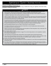
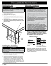
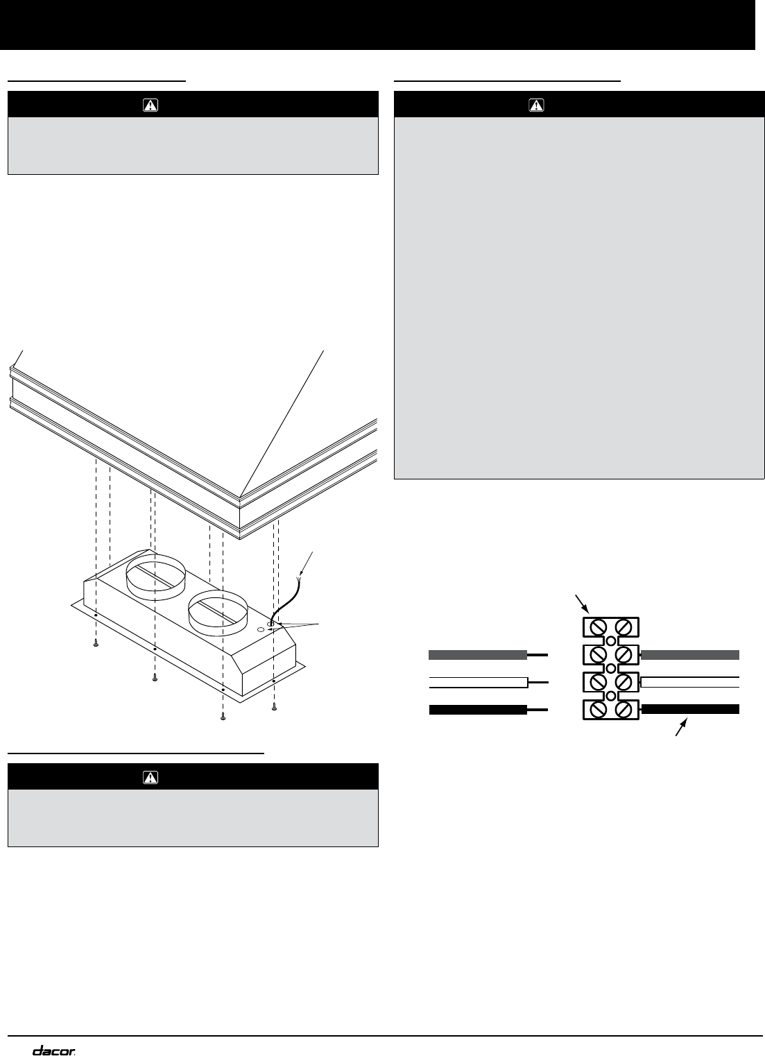
Models IVSR1 and IVSR2 only: 1. Route the wiring from
the in-line or remote blower into the IVS through one
of the electrical access holes in the hood. Connect
them to the remote blower (ILB8/REMP3) connection
terminal as shown below. Match wire colors.
Connect the pre-wired, white and green wires to the 2.
corresponding black, white and ground (green) wire
from the power source wiring. Use wire nut connectors
to secure the connections.
In s t a l l a t I o n In s t r u c t I o n s
Installing the IVS
WARNING
To avoid an electric shock hazard, do not connect the
wiring harness until after the IVS is installed in the cutout
and the duct work is installed.
If installing a hood liner (Dacor series IHL) install it 1.
before installing the IVS.
Remove the filters from the IVS.2.
The IVS comes pre-wired from the factory. Insert the 3.
unit into the cutout while routing the wiring harness to
the junction box.
While holding the IVS in place, attach it to the cutout 4.
with screws (not supplied) through the mounting holes
around the edge.
Installing the Duct Work
WARNING
During duct installation, make sure there are no
obstructions that keep the damper flaps on the top of the
IVS from opening.
Models IVSR1 and IVSR2 only: Install the remote or 1.
in-line blower (see page 5 for specifications) according
to the blower installation instructions.
Install the duct work starting from the hood working 2.
toward the outside vent. Observe the specifications
on pages 4 and 5. Fasten all joints with sheet metal
screws and seal with duct tape or certified silver tape.
The duct work must be air tight. Use a minimum of two
(2) sheet metal screws at every duct joint. Seal all duct
joints with a high quality duct tape.
L1
N1
Gnd
GREEN
WHITE
BLACK
GREEN
WHITE
BLACK
Not used
Wires connected to hood
wiring harness, do not remove
ILB/REMP wiring terminal
inside hood
Wires from in-line/remote
blower
Electrical
Access
Holes
Electrical
Wiring
Harness