


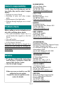

Page 4
•
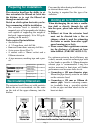
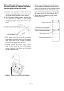
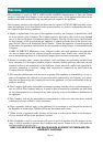
Draw a fine vertical line on the wall from
the rear-centre of the hob to the ceiling.
• Draw another line, horizontal this time,
where the bottom edge of the hood
should be. (A minimum distance be-
tween the hob and the hood of 750mm
is recommended.)
• Take the template card and separate the
ceiling mounting template from the hood
mounting template by cutting along the
indicated line.
• Using masking tape, stick the ceiling
mounting template to the wall directly
below the ceiling and centered on the
vertical line.
Installation..
Installation sequence;
1. Extractor unit / chimney brackets.
2. Top chimney duct
3. Bottom chimney duct
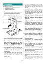
• Carefully remove the extractor hood and
the components from the packaging.
• Remove the grease filters.
• In a similar fashion stick the hood mount-
ing template on the wall ensuring that the
centre-lines line up with those drawn on
the wall.
• Note that the holes marked on the tem-
plate cater for both 600mm and 900mm
wide models. Please ensure that you only
use those markings relating to the model
you have purchased.
Holes for Triangular 600 are marked
with a (1).
Holes for Triangular 900 are marked
with a (2).
Holes not marked are common to all
models.
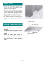
• For mounting the chimney brackets, drill
6 holes, 5mm in diameter and 45mm deep
into the wall as indicated on the mounting
template.
• For mounting the extractor hood, drill 4
holes, 8mm in diameter and 60mm deep
as indicated on the mounting template.
• Once all the holes have been drilled the
templates must be removed.
• Push the 5mm Dia. wall plugs through the
holes in the chimney mounting brackets.
Insert the plugs into the drilled holes to-
gether with the chimney mounting bracket
and fasten securely.
• Push the 8mm Dia. wall plugs into the
8mm Dia. holes ensuring that they are
flush with the wall.
• Partially screw two 6mm Dia. screws into
the two top wall plugs leaving them to
protrude about 10mm.
• Lift and hook the extractor hood over and
onto the two protruding screws through
the key-hole slots provided at the top of
the extractor hood frame.
• Insert the other two 6mm Dia. screws
through the holes inside the extractor
hood housing and into the 8mm Dia wall
plugs.
• Align the extractor hood with the centre
and horizontal lines before tightening all
four 6mm screws.
CUT TEMPLATE
TOP OF CEILING
LINE FROM CENTRE
OF STOVE TO CEILING
750
CEILING MOUNTING TEMPLATE
HOOD TEMPLATE
HORIZONTAL
LINE
CEILING MOUNTING
BRACKET POSITION