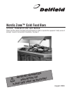
Nordic Zone Salad Bar Service and Installation Manual
For customer service, call (800) 733-8829, (800) 773-8821, Fax (989) 773-3210, www.deleld.com
2
Nordic Zone Salad Bar Service and Installation Manual
3
For customer service, call (800) 733-8829, (800) 773-8821, Fax (989) 773-3210, www.deleld.com
In most instances, the salad bar units will arrive at the job site
uncrated, and caution must be taken not to damage any exterior
surfaces when moving into position. All internal components
including glass and mirrors will be shipped intact within the unit.
The area where the salad bar is to be located must be clean and the
oor level to assure a satisfactory installation.
In the appropriate location, units must be leveled with the nished
work height top of Corian
®
to be approximately 34” above nished
oor. Make sure units are level left to right as well as front to back.
The units are mounted on 6” high legs which can be adjusted up to 1”.
Corian
®
adhesive (supplied) is to be applied between Corian
®
surfaces where they adjoin at center for proper moisture sealing.
Once the Corian
®
adhesive has been applied the units are ready to
be connected together where noted “spline here.” The locations are
directly behind the front nosing, below the upper front air diffuser,
and at the rear of the unit. Fasteners will be pre-installed within the
spline locations. Clean the units. Remove any excess silicone or
adhesive that may have squeezed out after splining units together.
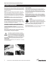
With sufcient help (4-5) individuals, slowly push the connected units
“evenly” back to the wall at the rear. Make sure that all stubbed out
electrical, refrigeration lines, and plumbing lines clear the cabinet
structure. If not, make any necessary adjustments to clear these
components. Once the units are secure against the wall at the rear,
double check for level.
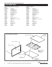
Locate and install Corian
®
rear and side splashes using adhesive
supplied. It may be necessary to trim pieces slightly to t.
REFRIGERATION INSTALLATION
If the condensing units are to be set on the roof of the building, it
must be mounted on beams supplied by the roong contractor or the
refrigeration contractor.
The condensing units must be a minimum of three feet apart to assure
proper air ow. Before the salad bar units arrive the refrigeration lines
must be installed from the condensing units down through the ceiling
and the rear wall and stubbed out per the drawing supplied to the
installer. The suction line should be 5/8 inch and the liquid line should
be 3/8 inch for most installations. The pipe insulation should be 1/2
inch wall thickness. A “p” trap must be installed at the lowest point
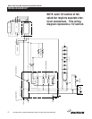
of the refrigeration lines. The electrical power supply must also be
stubbed through the rear wall.
The liquid line should be insulated if exposed to sunlight on roof
installations. All refrigeration lines must be secured to prevent
excessive vibrating or kinking of the copper tubing. Drain lines must
be installed to the drain stub on the bottom of the evaporator housing.
The drain must have proper slope to insure good drainage from the
evaporator pan. A minimum vacuum of 200 microns must be reached
before charging the units with R-404A refrigerant. The system must
be charged under a heat load with R-404A until the sight glass is clear.
Normal installations will require approximately 9lbs. of refrigerant for
each system.
All panels and covers must be installed in the proper locations and
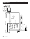
the defrost timer must be set for the proper time. Defrost time for
normal installations should be 15 minutes every three hours and the
thermostat setting should be for 37º degrees box temperature.
NOTE: do not change setting of defrost timer or
thermostat. See page #4 for complete operation
instructions.
INSTALLATION
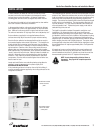
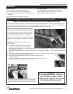
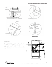
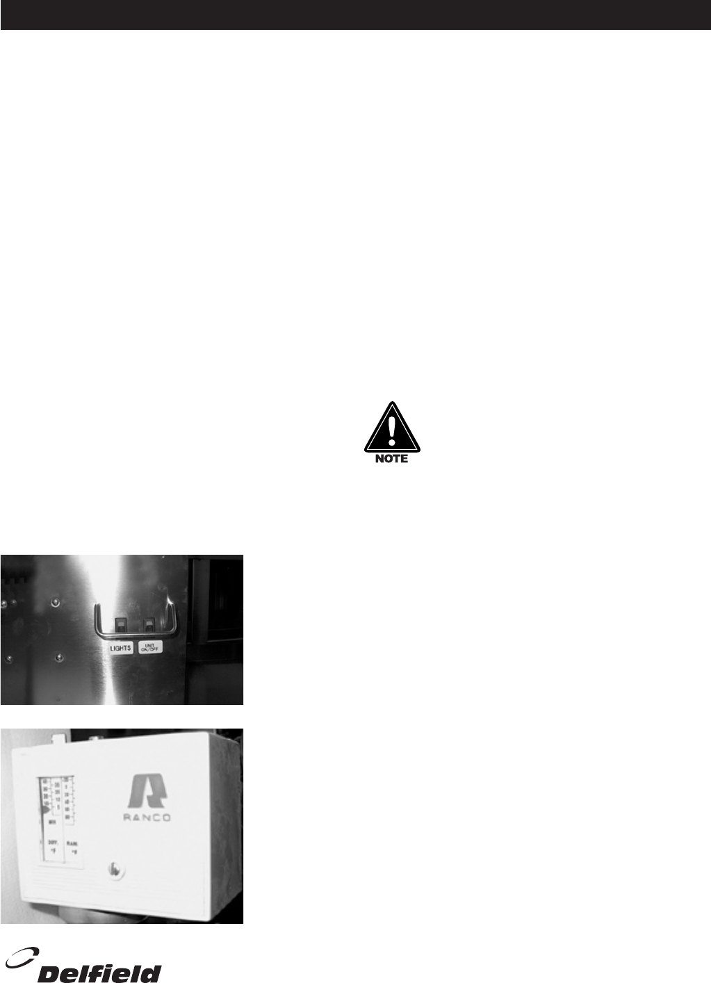
On/Off Switch located
behind the center
panel.
Thermostat located
behind the On/Off
switch panel.


