


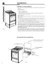

18
ቤ
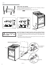
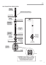
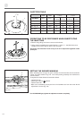
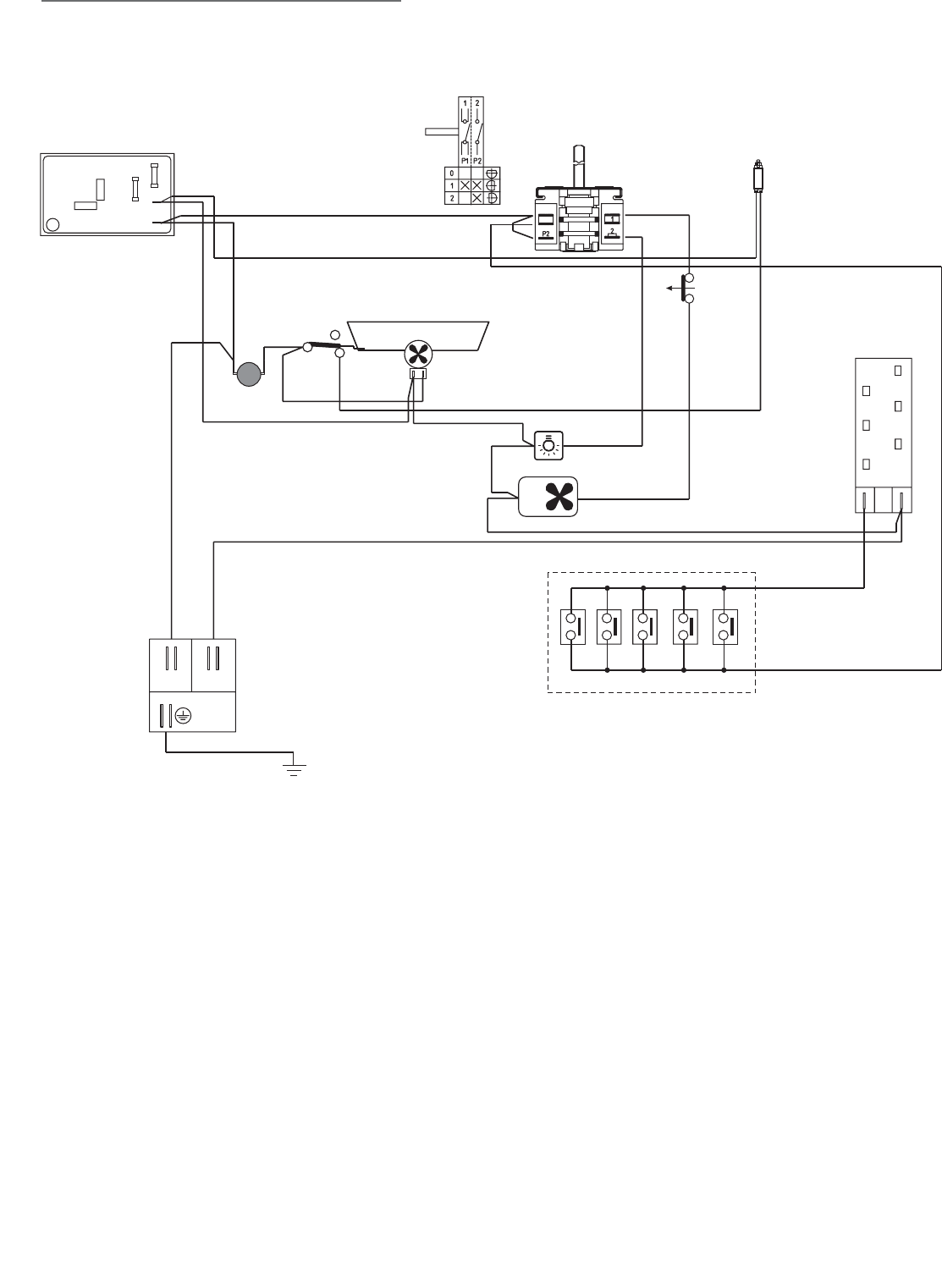
WIRING DIAGRAM
Fig. 3.2
P1
F1
MS
AS
CF
N/7
L/8
S1
PA
TL3
V
T
LF
EC
A
M
N
L
ELECTRIC DIAGRAM KEY
F1 Switch
MS Security microswitch
S1 Cooling fan safety lamp
LF Oven lamp
AS Air switch
V Fan
TL3 Thermal overload
PA Ignition switches group
A Ignition coil
EC Electronic clock
CF Cooling fan
M Terminal block
T Earth connection