


8
ቢ
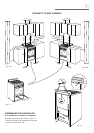
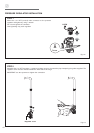
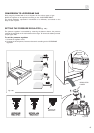
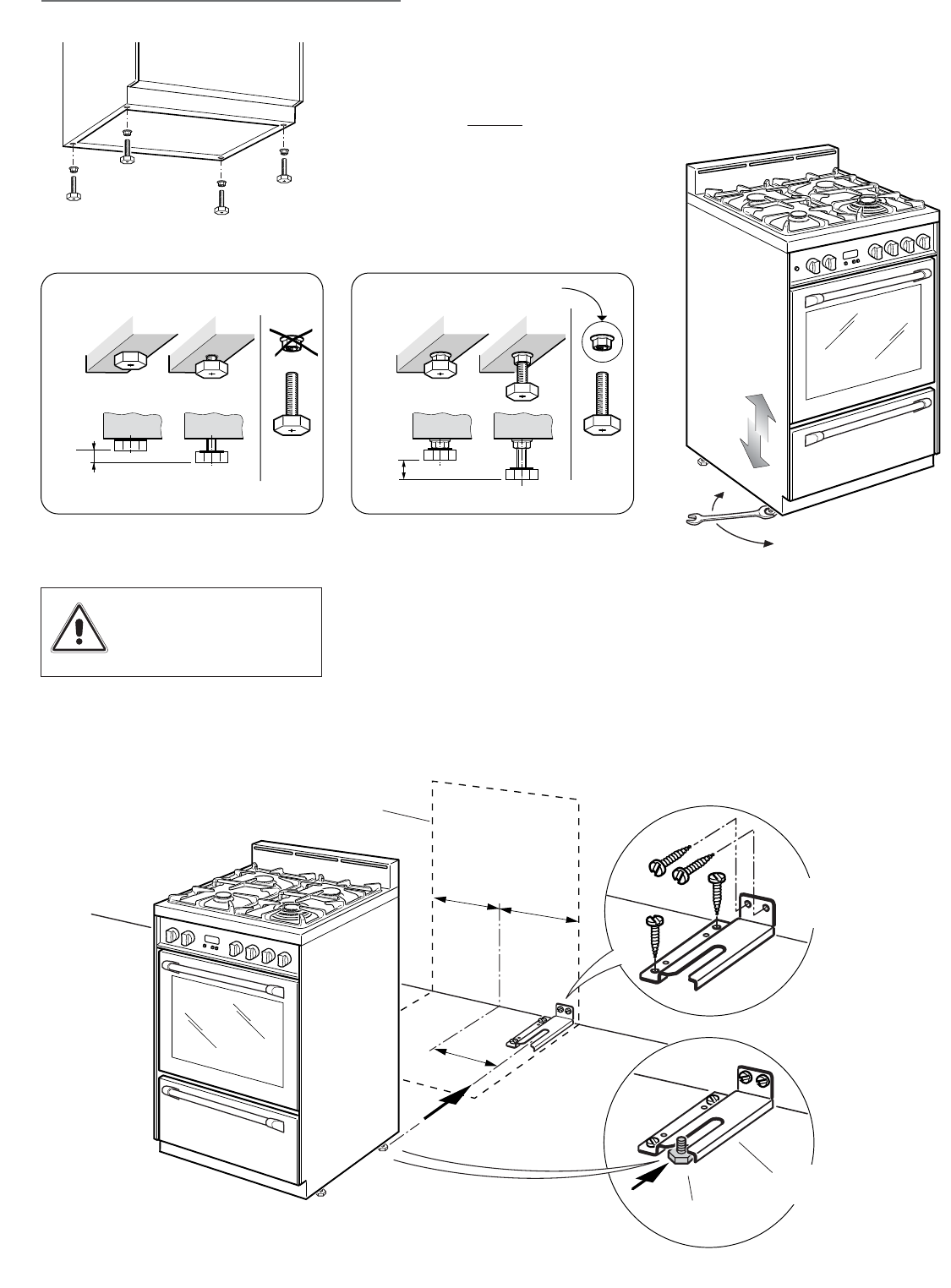
LEVELLING THE RANGE
The range is equipped with 4 LEVELLING FEET and may be levelled by screwing or
unscrewing the feet with a spanner (fig. 1.8).
It is important to observe
the directions of figures 1.6, 1.7a, 1.7b.
+ 8 mm
+ 5/16"
+ 8 mm
+ 5/16"
0 mm
0"
+ 20 mm
+ 25/32"
Fig. 1.6
Fig. 1.7a Fig. 1.7b
Fig. 1.8
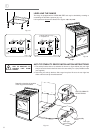
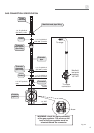
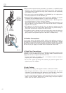
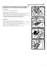
ANTI-TIP STABILITY DEVICE INSTALLATION INSTRUCTIONS
1. The anti-tip bracket has to be attached as shown on figure below (only rear right
side), it has to be fixed on the floor and on the rear wall by no. 4 (four) suitable screws
(not supplied).
2. After fixing the anti-tip bracket, slide range into place. Be sure the rear right foot
slides under the anti-tip bracket attached.
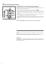
=
=
(260 m
m
)
10" 15/64
Dotted line showing the position
of the range when installed
ANTI-TIP STABILITY
DEVICE FIXING
Rear right
feet of range
Fig. 1.9
Anti-tip stability
device
Supplied with the range
in a separate kit
YOU MUST USE STABILITY
ANTI TIP BRACKET TO
PREVENT UNIT FROM
TIPPING.