


10
ELECTRICAL REQUIREMENTS
■ The appliance must be connected to the mains checking that the voltage correspon-
ds to the value given in the rating plate and that the electrical cable sections can
withstand the load specied on the plate.
■ A suitable isolating switch providing full disconnection from the mains power supply
shall be incorporated in the permanent wiring, mounted and positioned to comply with
the local wiring rules and regulations. The isolating switch must be of an approved
type and provide a 3 mm air gap contact separation in all poles (or in all active [phase]
conductors if the local wiring rules allow for this variation of the requirements).
■ The isolating switch shall be easily accessible to the customer with the cooktop installed.
■ The power supply cable must not touch the hot parts and must be positioned so that it
does not exceed 75°C above ambient.
■ To connect the appliance to the mains electricity supply, do not use adapters, reducers
or branching devices as they can cause overheating and burning.
N.B. The connection of the appliance to earth is mandatory.
If the installation requires alterations to the domestic electrical system call a qualied elec-
trician. He should also check that the domestic electrical system is suitable for the power
drawn by the appliance.
Replacing the power cord (not supplied with the appliance) must be done by a qua-
lied electrician in accordance with the instructions supplied by the manufacturer
and in compliance with established electrical regulations.
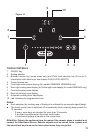
CONNECTION OF THE POWER SUPPLY CABLE
Important! This cooktop must be connected to the electricity supply only by an au-
thorised person.
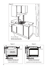
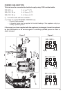
To connect the feeder cable to the hob it is necessary to carry out the following operations:
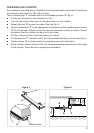
■ Unhook the terminal board cover “A” by inserting a screwdriver into the two hooks “B”
(g. 7). Open completely the terminal block cover “A”.
■ Unscrew the screw “C”, then unhook the cable clamp “D” by inserting a screwdriver
into the hook “E”. Remove completely the cable clamp “D” (g. 7).
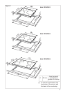
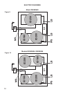
■ Connect the phase, neutral and earth wires to terminal board “F” according to the
diagrams in g. 8; the U bolts “G” (g. 7) shall be used as indicated in the diagrams
in g. 8 (they are supplied already tted to the terminals or inside the terminal board,
behind the cover).
■ Strain the feeder cable and block it with cable clamp “D” (by hooking hook “E” and
screwing screw “C”).
■ Close the cover “A” of the terminal board “F” (check the two hooks “B” are correctly hooked).
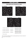
VOLTAGE AND POWER CONSUMPTION
Mod. DEIND603
220-240/380-415 V 3N~ 50/60 Hz 6700 W 29.13 A (diversity not applied)
Mod. DEIND604 - DEIND804
220-240/380-415 V 3N~ 50/60 Hz 7400 W 32.17 A (diversity not applied)