


26
ቤ
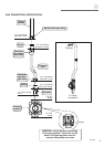
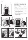
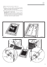
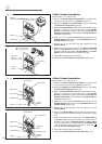
Conduit
Neutral Wire
Power Wires
Conduit Clamp
Terminal Block
Ground strap
Conduit
Bracket
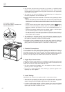
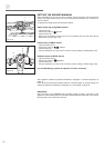
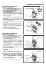
Conduit
Neutral Wire
Power Wires
Conduit Clamp
Terminal Block
Cut Ground strap
Conduit
Bracket
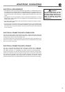
Grounding
Screw
Grounding Wire
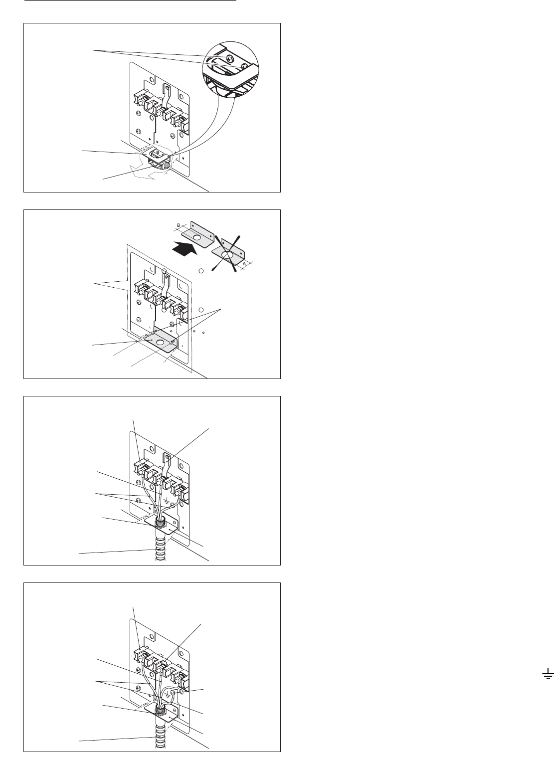
4-Wire Conduit Installation
(See Figures 3.1, 3.7, 3.8 and 3.10)
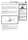
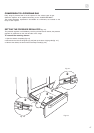
1. Remove the Terminal Block Access Plate on the back of the
range by unscrewing the 4 fixing Screws (Figure 3.1).
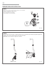
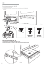
2. Remove the Bracket and Strain Relief group by unscrewing
the Bracket Fixing Screws (Figure 3.7).
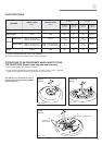
3. Mount the Conduit Bracket (supplied with the range in a sep-
arate kit - make sure you are using the correct Conduit
Bracket as indicated in Figure 3.8) inside the Opening For
Electrical Connection by screwing the 2 Fixing Screws (as
indicated in Figure 3.8).
4. Feed 1/2” (1.3 cm) trade size Conduit through the hole in the
Conduit Bracket and secure to the Conduit Bracket with a
Conduit Clamp (Figure 3.10).
5. Remove the 3 wire terminal nuts and washers from the
Terminal Block.
6. Remove the Ground Strap from the frame of range and ter-
minal by removing its screw and cutting it as shown in Figure
3.10.
7. Plug the terminal holes of conductors. The Neutral Wire of
the Power Cord must be connected to the neutral terminal
located in the center of Terminal Block; the Power Wires
must be connected to the outside terminals; the Ground Wire
must be attached to the frame of range by using the
(Ground) identified Grounding Screw.
8. Plug washers and tighten nuts securely.
9. Assemble the Terminal Block Access Plate (Figure 3.1).
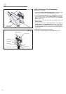
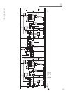
Fig. 3.9
Fig. 3.10
Strain Relief
Bracket
Bracket
Fixing Screws
Conduit
Bracket
Opening For
Electrical
Connection
Fixing Screws
B: D=
7
/
8
" (22.5 mm)
A: D=1"
9
/
64
(29 mm)
3-Wire Conduit Installation
(See Figures 3.1, 3.7, 3.8 and 3.9)
1. Remove the Terminal Block Access Plate on the back of the
range by unscrewing the 4 fixing Screws (Figure 3.1).
2. Remove the Bracket and Strain Relief group by unscrewing
the Bracket Fixing Screws (Figure 3.7).
3. Mount the Conduit Bracket (supplied with the range in a sep-
arate kit - make sure you are using the correct Conduit
Bracket as indicated in Figure 3.8) inside the Opening For
Electrical Connection by screwing the 2 Fixing Screws (as
indicated in Figure 3.8).
4. Feed 1/2” (1.3 cm) trade size Conduit through the hole in the
Conduit Bracket and secure to the Conduit Bracket with a
Conduit Clamp (Figure 3.9).
5. Remove the 3 wire terminal nuts and washers from the
Terminal Block.
6. Plug the terminal holes of conductors. The Neutral or Ground
Wire of the Power Cord must be connected to the neutral
terminal located in the center of Terminal Block. The Power
Wires must be connected to the outside terminals.
7. Plug washers and tighten nuts securely.
8. Assemble the Terminal Block Access Plate (Figure 3.1).
Fig. 3.7
Fig. 3.8