


107304
For more information, visit www.desatech.com
For more information, visit www.desatech.com
13
13
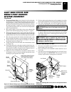
INSTALLATION FOR HORIZONTAL
TERMINATION
1. Determine the route your horizontal venting will take.
Note:
The location of the horizontal vent termination on the exterior
wall must meet all local and national building codes and must
not be easily blocked or obstructed.
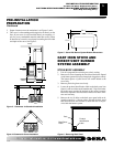
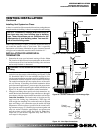
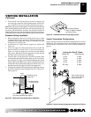
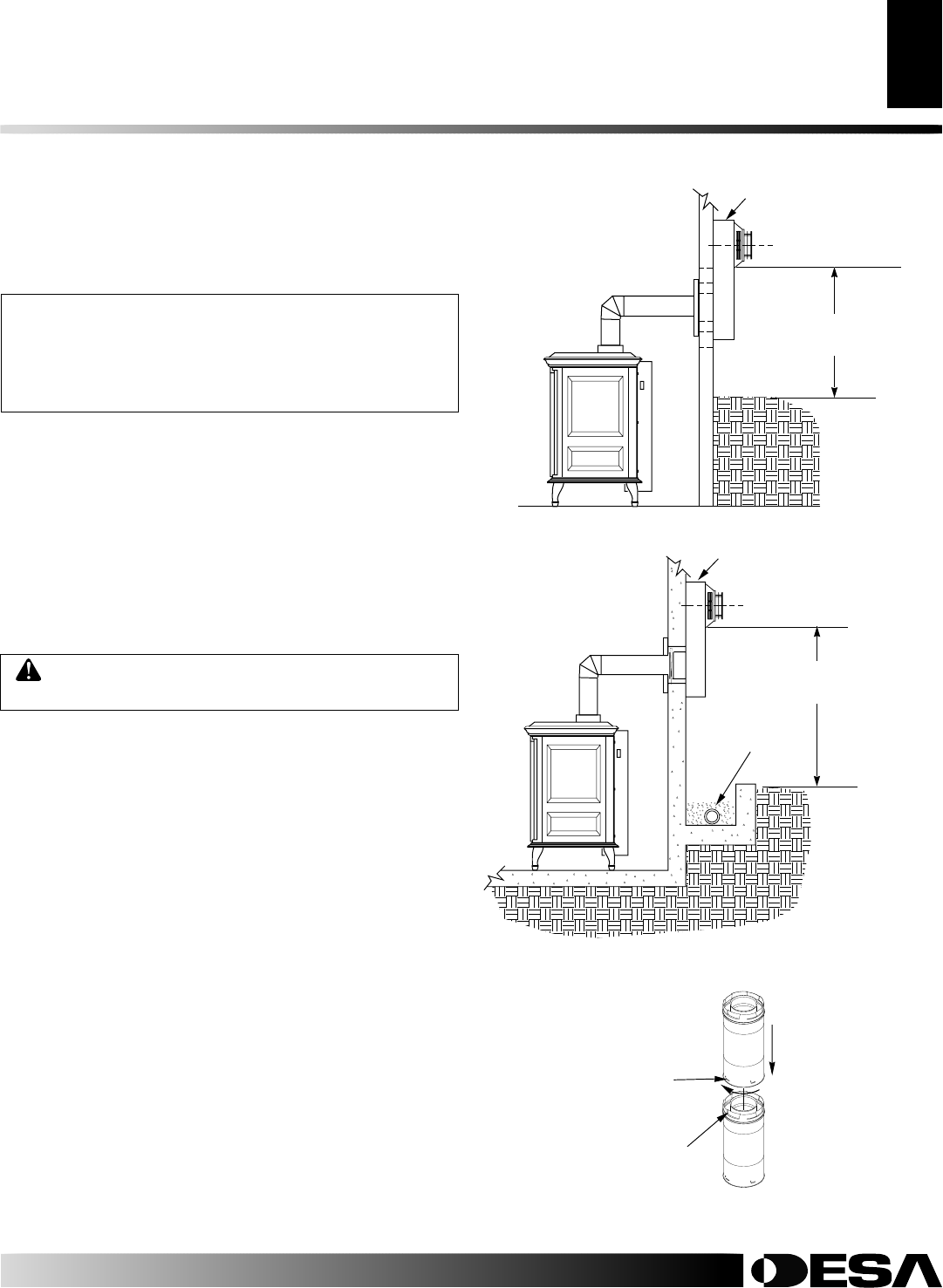
Snorkel terminations are available for terminations requiring a
vertical rise on the exterior of the building (see Figures 22 and
23). Snorkel kit VKS-47-K is also available (see page 19). Fol-
low the same installation procedures used for standard horizon-
tal termination with the exception of the external wall firestop.
The snorkel termination does not require the use of the exter-
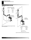
nal wall firestop. If installing the snorkel termination below
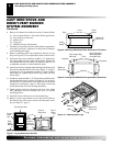
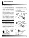
grade (basement applications), you must provide proper drain-
age to prevent water from entering the snorkel termination (see
Figure 23). Do not back fill around the snorkel termination.
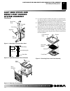
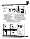
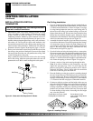
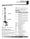
2. Vent pipes and fittings have special twist-lock connections. As-
semble the desired combination of pipe and elbows to the appli-
ance adaptor with pipe seams oriented towards the wall or floor.
Twist-lock Procedure: The female ends of the pipes and fit-
tings have four locking lugs (indentations). These lugs will
slide straight into matching slots on the male ends of adjacent
pipes and fittings. (All connections must be sealed with high
temperature silicone sealant as specified in the second warn-
ing statement on page 12.) Push the pipe sections together and
twist one section clockwise approximately one-quarter turn
until the sections are fully locked. See Figure 24.
Note:
Hori-
zontal runs of vent must be supported every three feet. Use
wall straps for this purpose.
VENTING INSTALLATION
Continued
WARNING: Do not recess vent terminal into a wall
or siding.
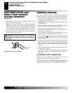
Figure 22 - Snorkel Termination
Snorkel
Figure 23 - Snorkel Termination with Drainage Pipe
12" Minimum
(305mm)
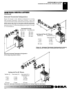
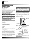
NOTICE: Treatment of firestops and construction of
the chase may vary from building type to building
type. These instructions are not substitutes for the
requirements of local building codes. You must fol-
low all local building codes.
Note:
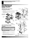
When installing in a chase, you should insulate the chase as
you would the outside walls of your home. This is especially
important in cold climates. Minimum air space clearance between
vent pipes and combustible materials and/or insulation is 1".
Installing Vent System in a Chase
A chase is a vertical box-like structure built to enclose venting that runs
along the outside of a building. A chase is not required for such venting.
Snorkel
Adequate
drainage
12" Minimum
(305mm)
Figure 24 - Vent Pipe Connections
Female
Locking Lugs
Male
Slots
Vent Pipe
VENTING INSTALLATION
Installation Planning (Cont.)
Installation for Horizontal Termination