


107304
For more information, visit www.desatech.com
For more information, visit www.desatech.com
14
VENTING INSTALLATION
Continued
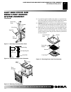
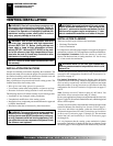
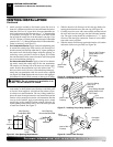
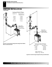
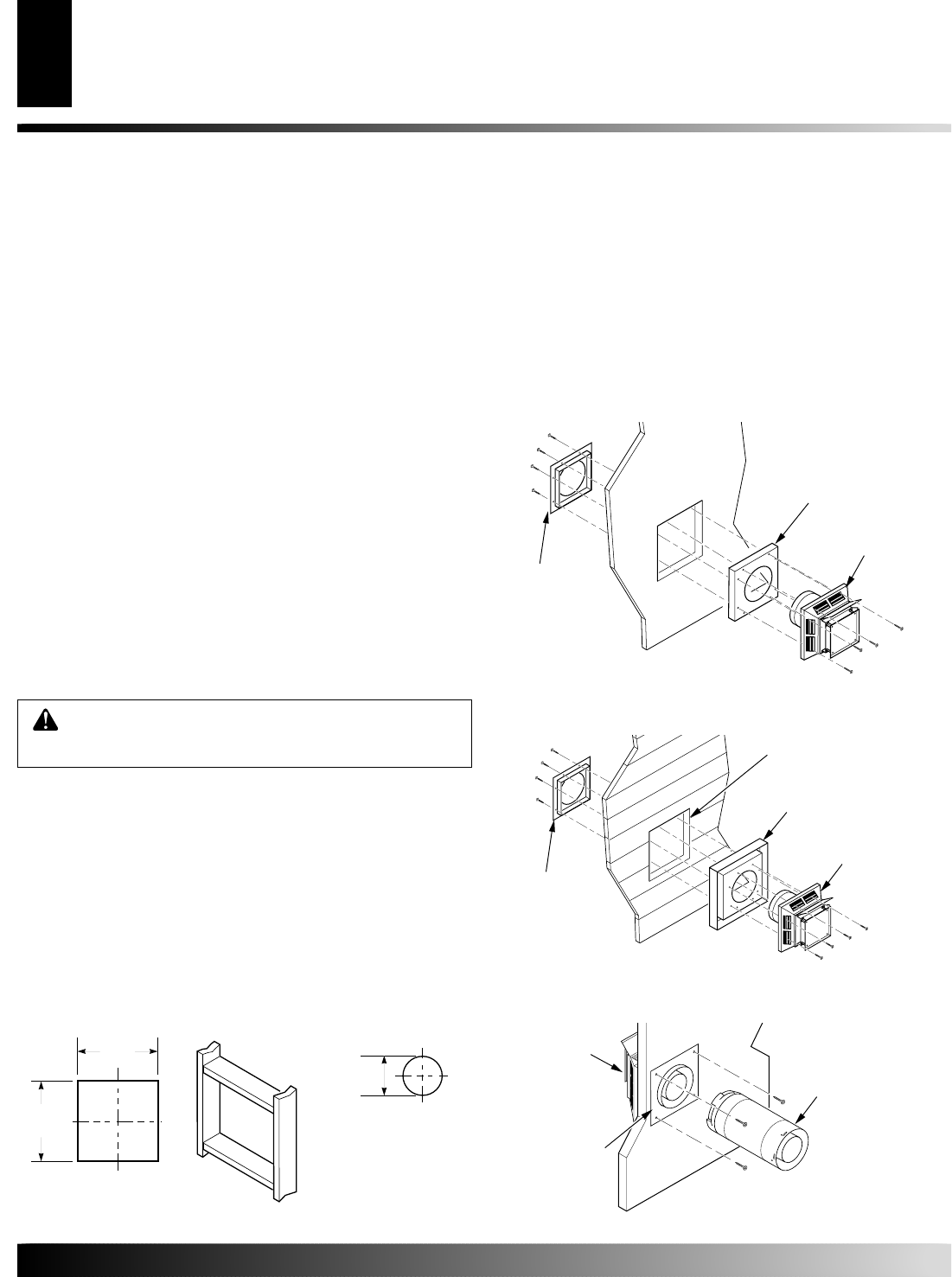
Figure 26 - Installing Horizontal Vent Cap with Exterior Wall
Firestop (Combustible Exterior)
WARNING: Do not recess vent termination in to
any wall. This will cause a fire hazard.
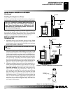
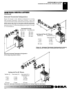
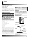
Figure 27 - Installing Vinyl Siding Standoff
Cut Vinyl Siding
Away to Fit
Standoff
Vinyl Siding Standoff
(Apply Mastic to All
Four Sides)
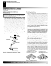
7
1
/
2
"
(190mm)
Vent Opening
Noncombustible Wall
(Framing
Detail)
10"
(254mm)
10"
(254mm)
Vent Opening
Combustible Wall
Vent O
p
ening
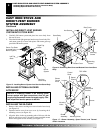
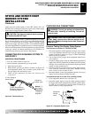
Figure 28 - Interior Wall Firestop
Interior Wall
Firestop
Exterior Wall Firestop
(Apply Mastic to All
Four Sides)
Vent
Termination
Vent
Termination
Interior Wall
Firestop
Interior Wall
Firestop
Vent
Termination
Horizontal
Vent Pipe
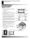
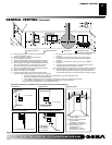
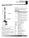
3. Attach vent pipe assembly to the burner system. Set stove in
front of it’s permanent location to insure minimum clearances.
Mark the wall for a 10" square hole (for noncombustible ma-
terial such as masonry block or concrete, a 7
1
/2" diameter hole
is acceptable). See Figure 25. The center of the hole should
line up with the center-line of the horizontal vent pipe. Cut a
10"x10" (254mm x 254mm) square hole through combustible
exterior wall (7
1
/2" [190mm] diameter hole if noncombustible).
Frame as necessary (see Figure 25).
4. For Combustible Exterior: Apply a bead of non-hardening mas-
tic around the outside edge of the exterior wall firestop. Posi-
tion the external wall firestop within the 10" square opening on
the exterior wall with firestop flanges inside the opening. At-
tach using screws provided as shown in Figure 26. Position
the vent termination in the center of exterior wall firestop with
arrow on termination pointing up.
For Noncombustible Exterior: Apply a bead of non-harden-
ing mastic around the outside edge of the vent termination.
The exterior wall firestop will not be necessary for this appli-
cation. Position the termination cap in the center of the 7
1
/2"
hole on exterior wall with arrow on termination pointing up.
Attach the vent termination with four wood screws supplied
(see Figure 26).
Note
: Replace the wood screws with appropri-
ate fasteners for stucco, brick, concrete, or other types of siding.
5. Use of a vinyl siding standoff is required when vinyl siding,
cedar shake, or other painted wood surfaces could melt, peel,
or discolor from trapped or wind driven flue exhaust (exces-
sive heat) near vent termination. The vinyl siding standoff re-
places the outer firestop between the vent termination and the
exterior wall to protect these exterior wall treatments. Bolt the
vent cap to the standoff. Apply non-hardening mastic around
outside edge of the standoff. Position standoff within the 10"
square opening on the exterior wall. Use wood screws provided
to attach the standoff. See Figure 27.
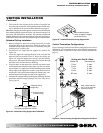
6. Slide the interior wall firestop over the vent pipe before con-
necting the horizontal run to the vent cap (see Figure 28).
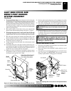
7. Carefully move the stove with vent assembly attached toward
the wall and insert the vent pipe into the horizontal termina-
tion. The pipe overlap should be a minimum of 1
1
/4". Apply
silicone to the outer pipe connection. Fasten all vent connec-
tions with screws provided.
8. Slide the interior wall firestop against the interior wall surface
and attach with screws provided (see Figure 28).
Figure 25 - Vent Opening Requirements
VENTING INSTALLATION
Installation for Horizontal Termination (Cont.)