


106828-01D
For more information, visit www.desatech.com
For more information, visit www.desatech.com
14
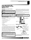
Test Pressures Equal To or Less Than 1/2 PSIG (3.5 kPa)
1. Close equipment shutoff valve (see Figure 31).
2. Pressurize supply piping system by either opening propane/LP
supply tank valve for propane/LP gas burner system or opening
main gas valve located on or near gas meter for natural gas burner
system, or using compressed air.
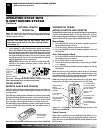
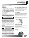
3. Check all joints from propane/LP supply tank or gas meter to equip-
ment shutoff valve (see Figure 32 for propane/LP or Figure 33 for
natural, page 15). Apply noncorrosive leak test solution to all gas
joints. Bubbles forming show a leak. Correct all leaks at once.
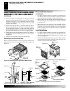
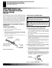
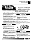
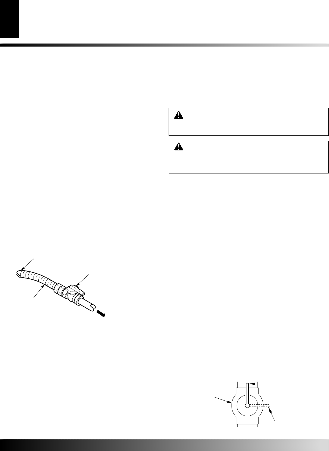
Figure 31 - Equipment Shutoff Valve
ON
POSITION
OFF
POSITION
Open
Closed
Equipment
Shutoff Valve
Pressure Testing Gas Supply Piping System
Test Pressures In Excess Of 1/2 PSIG (3.5 kPa)
1.
Disconnect appliance with its appliance main gas valve (control
valve) and equipment shutoff valve from gas supply piping
systems. Pressures in excess of 1/2 psig (3.5 kPa) will damage
burner system gas regulator.
2. Cap off open end of gas pipe where equipment shutoff valve
was connected.
3. Pressurize supply piping system by either opening propane/LP
supply tank valve for propane/LP gas burner system or opening
main gas valve located on or near gas meter for natural gas burner
system, or using compressed air.
4. Check all joints of gas supply piping system. Apply noncorro-
sive leak test solution to all gas joints. Bubbles forming show
a leak. Correct all leaks at once.
5. Reconnect burner system and equipment shutoff valve to gas
supply. Check reconnected fittings for leaks.
CHECKING GAS CONNECTIONS
WARNING: Test all gas piping and connections,
internal and external to unit, for leaks after installing
or servicing. Correct all leaks at once.
WARNING: Never use an open flame to check for
a leak. Apply noncorrosive leak test solution to all
gas joints. Bubbles forming show a leak. Correct all
leaks at once.
Installation Items Needed
• 5/16" hex socket wrench or nut-driver
• sealant (resistant to propane/LP gas, not provided)
1. Open lower door panel.
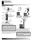
2. Route flexible gas line (provided by installer) from equipment
shutoff valve to burner system (see Figure 30). Route flexible
gas supply line and attach to valve.
3. Check all gas connections for leaks. See Checking Gas
Connections, column 2.
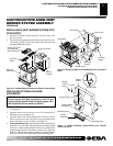
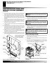
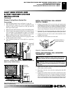
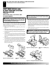
CONNECTING STOVE/BURNER SYSTEM TO
GAS SUPPLY
To Flare Fitting on
Control Valve
Flexible Gas Line from
Equipment Shutoff Valve
Provided by Installer
Equipment
Shutoff Valve
To Gas Supply
(Natural)
To External Regulator
(Propane/LP)
Figure 30 - Flexible Gas Line
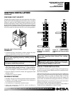
CAST IRON STOVE AND
B-VENT BURNER SYSTEM
INSTALLATION
Continued
We recommend that you install a sediment trap/drip leg in supply
line as shown in Figure 29, page 13. Locate sediment trap/drip leg
where it is within reach for cleaning. Install in piping system
between fuel supply and burner system. Locate sediment trap/drip
leg where trapped matter is not likely to freeze. A sediment trap traps
moisture and contaminants. This keeps them from going into burner
system gas controls. If sediment trap/drip leg is not installed or is
installed wrong, burner system may not run properly.
CAST IRON STOVE AND B-VENT BURNER SYSTEM INSTALLATION
Installing Gas Piping to Stove Location (Cont.)
Connecting Stove/Burner System to Gas Supply
Checking Gas Connections