


106828-01D
For more information, visit www.desatech.com
For more information, visit www.desatech.com
5
5
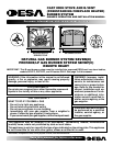
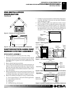
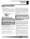
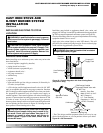
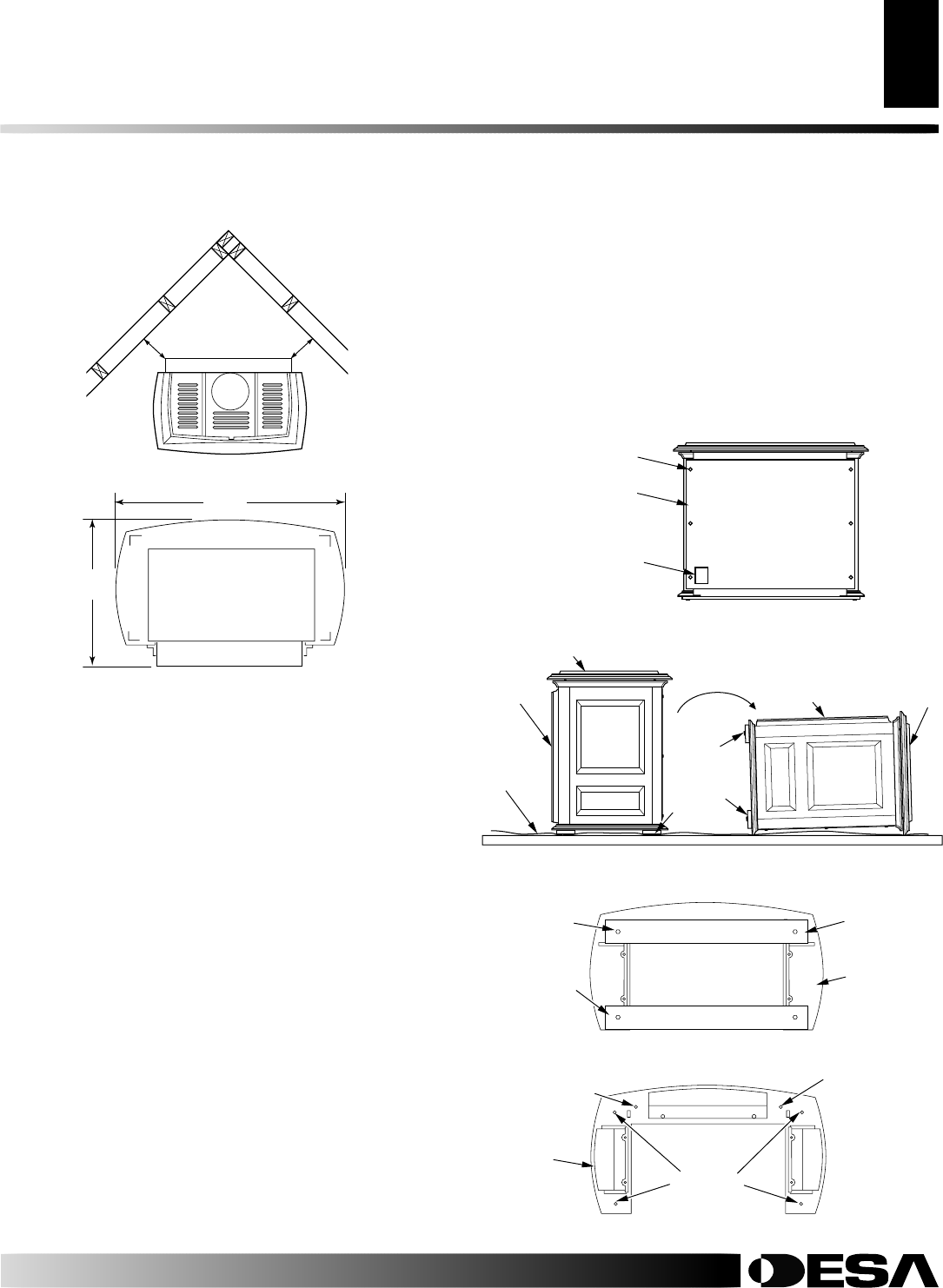
4"
4"
Figure 4 - Clearance for Corner Installation
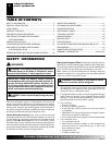
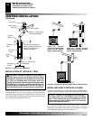
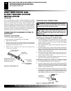
Figure 5 - Stove With Burner System Bottom Dimensions
PRE-INSTALLATION
PREPARATION
Continued
CAST IRON STOVE AND B-VENT
BURNER SYSTEM ASSEMBLY
STOVE BODY ASSEMBLY
1. Lift off corrugated box enclosing stove body crating.
2. Remove all screws fastening the wood frame enclosure. Spread
wood frame open and lift away from plastic-bagged stove body.
The bottom pieces of pallet wood will remain bolted to the
stove body.
3. Remove plastic bag from stove body.
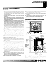
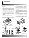
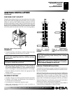
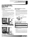
4. Locate the product identification label on the back panel (see
Figure 6) and record the model number and 7 digit serial num-
ber in the space provided in the back of this owner’s manual.
Retain this operation and installation manual for future refer-
ence and warranty.
5. Remove back panel from stove and discard (see Figure 6). Use
an adjustable wrench or a 10 mm socket. Remove six (6) bolts
and washers. Keep bolts and washers to reattach rear cover.
6. Remove all contents from inside stove cavity. Contents include:
(1) - Stove bottom (Discard - Not used with this application)
(4) - Legs with leg leveler bolts
(1) - Bottom door
(3) - Top grates
(1) - Hardware kit bag with fasteners
Figure 6 - Removing Back Panel
Bolt
Product
Identification Label
with Model and
Serial Numbers
Back Stove
Panel
Pallet
Wood
Bolted to
Bottom of
Stove
Body
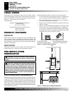
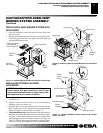
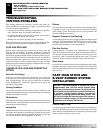
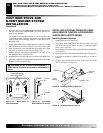
Figure 7 - Laying Down Stove On Side
Front of
Stove
Unit
Top of Stove Unit
Front of
Stove Unit
Top of
Stove
Unit
Drop
Cloth/
Blanket
7. Carefully lay stove body on back to attach bottom components to
stove body (see Figure 7). Rest stove on drop cloth or blanket to
avoid scratching stove edges.
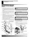
8. Remove remaining pallet wood attached to bottom of stove
body (see Figure 8). Use an adjustable wrench to remove bolts.
9. Fasten each leg to stove with four (4) M8 x 1.25 - 20mm bolts.
Use a flat washer and lock washer with each bolt. Tighten bolts
into threaded holes on stove body (see Figure 9 and Figure 10
on page 6). Use an adjustable wrench or a 12mm socket.
Figure 8 - Removing Pallet Wood From The Bottom of The Stove
Pallet Wood
Bolt Pallet
Wood
Bottom Of
Stove Unit
Front
Figure 9 - Locating Threaded Holes for Legs and Door Attachment
Leg Hole
Front
Door Hinge
Step Bolt Hole
Door Catch Bolt
With Adjustable
Hex Nuts Hole
Bottom Of
Stove Unit
PRE-INSTALLATION PREPARATION
Location and Space Requirements (Cont.)
CAST IRON STOVE AND B-VENT BURNER SYSTEM ASSEMBLY
Stove Body Assembly
26
1
/4"
19
1
/2"
Front