


gned for the type and diameter of the connection pipe
used, and screwed joints should be sealed with a joining
compound approved for use with bottled gas.
The gas supply pipe should be connected to the gas inlet
pipe on the right hand side of the gas control valve by
means of a suitable threaded compression coupling.
In making the connection to the refrigerator, a union gas
cock of an approved type bottled-gas must be incorpora-
ted in the supply line in a position which is readily acces-
sible to the user. For eventual servicing purposes, the
union should be on the outlet side of the cock and the
pipework should be positioned so as not to prevent the
refrigerator from being readily withdrawn.
ELECTRICAL CONNECTION 230VAC
Check that the voltage stated on the data plate is the
same as the mains voltage in use (230 V).
Plug the 230 V refrigerator power cord into an easily
accessible wall socket.
Electrical leads must be routed and secured
so that they cannot come into contact with hot
or sharp parts of the refrigerator.
12 V Supplies
Connect the refrigerator to the vehicle battery by a direct
cable. To avoid a voltage drop, the cross sectional area
of the connecting cable between battery and refrigerator
must be at least 2.5 mm² if the distance is less than 9
meters, and at least 4 mm² if the distance is more than 9
meters. To ensure satisfactory operation, the positive
lead must be fitted with a fuse rated at max. 16 A.
To prevent the refrigerator from draining the battery,
make sure that the current supplied to the caravan is cut
off when the vehicle engine is not running, for example
by fitting an ignition control relay.
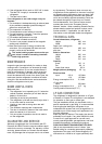
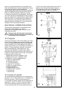
Diagramme for the mains installation: FIG.1
Diagramme for the 12 V installation: FIG.2
The notations in the wiring diagramme are:
A. Electronic igniter/reigniter
B. Electrode (at burner)
C. 12 V heating element
D. Switch for 12 V operation
E. Switch for reigniter (gas op.)
F. Electric thermostat
G. Heating element, 240 V
H. Switch for 240 V operation
J. Terminal block
L. Terminal block
12 V supply of reigniter
FIG.2 shows the wiring diagramme of the refrigerator as
delivered. The 12 V supply enters at (L). The reigniter (A)
is fed via two wires (1) and (2) at terminal block (L).
It is advisable to feed the reigniter and the lighting from a
separate 12 V source. To do this: remove the wires (1)
and (2) and connect the supply as is shown in FIG.3.
In some executions there in an extra terminal block (J),
of FIG.2. In this case one disconnects the wires as
said above but connects the separate supply to
(J).The reigniter should not be connected directly
to a battery charger but only over a battery.
12
FIG.1
230V
FIG.2
FIG.3