


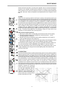
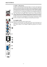
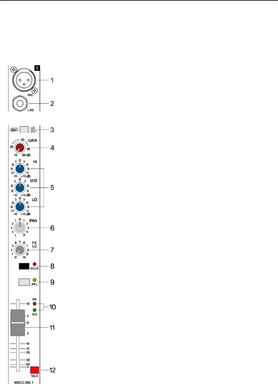
6. PAN
The setting of the PAN control defines the input signal’s position within the stereo image.
When set to its center position, the audio signal is fed with equal levels to the left and right
master busses. The PAN section’s design ensures that the overall relative level of an audio
signal is maintained, no matter to what position within the stereo image the PAN control is
set.
7. FX1/2
Using the FX1/2 control lets you route the corresponding input signal to the integrated digital
effects units FX1 or FX2 at variable levels. In this way assigning special effects to musical
instruments or vocals is fairly simple. When establishing an effect-mix, it is good advice to
start with all FX-controls set to their center position. From this point you can increase or
reduce the effect’s intensity, depending on your personal preferences. Please make sure
to carefully monitor the PEAK LED’s in the FX1/2 channels during a performance. The
indicator should only light briefly at the occurrence of peak signals. If the LED lights
constantly, it is strongly recommended to lower the affected channels’ send levels at their
FX1/2 controls. For further information, please refer also to the paragraphs on the FX1/2
units.
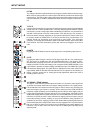
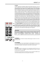
8. MUTE
Engaging the MUTE button mutes the audio signal of the corresponding input channel.
9. PFL
Engaging this button assigns a channel’s audio signal to the PFL bus. For monitoring the
PFL bus signal via headphones slide the PHONES MIX fader in the direction “PFL”.
Simultaneously assigning more than one channel to the PFL bus is possible, while the
individual channel’s volume fader setting is not recognized (PRE FADER LISTEN). Once
a PFL button is pressed, the master display automatically enters PFL/PGM mode (yellow
LED below the display lights). The right LED-chain indicates the level of the master audio
signal (PGM), while the left LED-chain indicates the PFL bus signal level. This allows you
setting a signal’s correct level or making special EQ-adjustments without the need of
including it in the main mix.
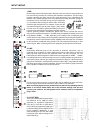
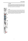
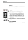
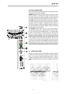
10. SIGNAL / PEAK indicator
The Signal / Peak indicator provides optical information of a channel’s actual signal level
at all times. As already mentioned in the chapter “setting instructions”, the “signal present”
LED should blink in the rhythm of the incoming signal. If this is not the case, increasing the
input level using the gain control is necessary. On the other hand, if the PEAK LED blinks
frequently or lights constantly, the corresponding channel is likely to enter clipping and you
have to reduce amplification using the gain control. The “signal present” LED lights at levels
30dB below clipping while the peak LED lights at a level of 8dB below the occurrence of
overdrive. To prevent the mixer’s input channels from clipping, which for instance may be
caused by increasing volumes, keeping an eye on these indicators during operation is a
good idea, too. Of course, engaging a channel’s PFL-button allows monitoring that channel’s
level via the display in the master section. Be sure to only engage the PFL-key of the channel
that you are about to adjust. The channel’s level is displayed in the master display’s left
LED-chain. Here as well, make sure that the red LED (+12dB) lights only briefly during
dynamic peaks.
INPUT/MONO
28