


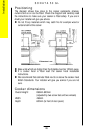

3. FITTING THE STABILITY BRACKET
It is recommended that if the appliance is to be installed with a flexible supply pipe a stability bracket
(SK.4729.A) is fitted and is available from your supplier (see Important Safety Requirements, Page 33).
These instructions should be read in conjunction with the leaflet packed with the stability bracket.
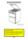
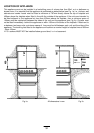
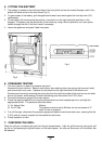
1. Place the appliance in its intended position and level appliance.
2. Mark off 250mm from the left hand side of the appliance as shown in dimension 'A', Fig 2a. This is the
centre line of the fixing bracket.
3. Draw a line 100mm from the front edge of the levelling feet (see Fig 2a) and remove appliance from
its position. Mark off dimension 'B' (see Fig 2a) back from this line on the centre line of the bracket to
locate the front edge of the lower bracket. Fix lower bracket (with two fixing holes) to the floor then
measure the height from floor level to engagement edge on back of appliance, dimension 'C' of Fig. 2b.
4. Assemble upper bracket to lower bracket so that underside of bracket is dimension 'C' +3mm above
floor level. (see Fig. 2b).
Reposition appliance and check that top bracket engages into appliance back as shown in Fig. 2b.
Fig.2a Fig.2b
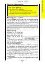
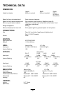
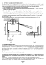
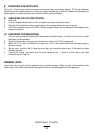
4. CONNECTING TO GAS
This appliance is designed to be installed with an appliance flexible connection only. Supply piping should
not be less than R³/8. Connection is made to the Rc ½ (½" B.S.P.) female threaded entry pipe located just
below the hotplate level on the rear left hand side of the appliance.
NOTE: ONLY LIQUID SEALANTS TO
BE USED WHEN INLET GAS PIPE IS FITTED TO RESET VALVE I.E.: DO NOT USE P.T.F.E.
SEALANT TAPE.
Check for gas soundness after connecting the gas supply.
The gas bayonet connector must be fitted in the shaded area indicated in Fig. 3. Take into account that it
must be possible to pull the appliance forward sufficiently. The hose must not get caught on the stability
bracket.
IMPORTANT: FLEXIBLE TUBING USED MUST COMPLY WITH BS. 669 CURRENT EDITION.
L.P.G. FLEXIBLE CONNECTIONS MUST BE OF A TYPE SUITABLE FOR L.P.G. AND CAPABLE OF
OPERATION UP TO 50 mbar AND TO CARRY A RED STRIPE, BAND OR LABEL.
36
100mm
487mm (B)
(A)
250mm
(C)