


20
C.4.1 ALARMS
The electronic board manages two kinds of alarm system:
- HACCP for monitoring and storing high temperature alarms.
HACCP alarm states are signalled by the sounding of the
buzzer, the blinking of the red HACCP indicator light and the
appearance of an alarm message on the display.
- SERVICE ALARMS for storing and managing all the alarms on
the electronic board (except the high temperature and blast
chilling cycle end error alarms).
C.4.1.1 HACCP ALARMS
For managing the chamber high temperature alarm and the
blast chilling cycle end error alarm.
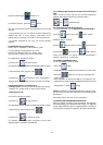
If there is no current alarm: the “TEMPERATURE” display
reads ‘none’, and the “TIME” display is switched off.
If there is a current alarm the “TEMPERATURE” display shows
the alarm number “ AL 1”, AL 2", etc., and the “TIME” display
gives the description of the alarm (see section below).
To display the alarm, enter the utility and use the
buttons to scroll until the messages appear: “AL 1”, “AL 2” and
so on.
After displaying the last alarm, the ‘——’ message will appear
on the alarm display, and if nothing is pressed for 12 seconds
the unit will automatically go back to the main menu.
To cancel the alarms, press
+ together for 5
seconds.
ATTENTION: The reset function is disabled if the operator did not
see the stored alarms. When the reset function is enabled the
message “RES” appears on the TEMPERATURE display.
C.4.1.1.1 DESCRIPTION OF ALARMS
- HIGH TEMPERATURE ALARM
The display shows:
• the “Batch (number) Ht (maximum temperature reached) °F/
°C Start Date Time End —-”, if the alarm is still active
e.g. Batch 01 Ht 59°F / 15°C Start 25-10-01 15.48 End ——
• the “Batch (number) Ht (maximum temperature reached) °F/
°C Start Date Time End Date OrTime”, if the alarm has ended
e.g. Batch 01 Ht 59°F / 15°C Start 25-10-01 15.48 End 25-10-
01 17.48
where:
Start Date Time indicates the start of the alarm, End Date Time
indicates the end of the alarm (“Date” format: DD-MM-YY, “Time”
format: HH.MM; ).
- CHILLING CYCLE END ERROR ALARM
This check ensures that a food (core) probe blast chilling/
freezing cycle ends correctly.
If a cycle does not end correctly, a “Chilling time out of limits”
alarm is generated and the display reads:
Batch (number) Ot (chilling time)MIN Start Date Time End date
Time”
e.g. BATCH1 Ot 250MIN Start 25-10-01 15.48 End 25-10-01
19.58.
where (number) indicates the current day’s batch number, Start
Date Time indicates the cycle start and End Date Time the cycle
end.
WHAT IS A BATCH NUMBER? Each blast chilling cycle (SOFT/
HARD chilling, freezing) will be identified by a progressive
number(1,2, ... ), known as the “BATCH NUMBER”. This refers
to the current day and will be reset to ‘0’ at the start of each new
calendar year.
N.B. There are no cycle end alarms in timed chilling/freezing.
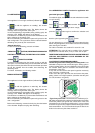
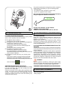
IMPORTANT:
in the event of a power failure, the display shows the “no
power” alarm with red indicator
. This alarm can be
displayed by scrolling with the utility keys. The appliance will
then restart from exactly where it stopped.
C.4.1.2 SERVICE ALARMS
There are two types of service alarm:
- type “b” (user) which do not require service center assistance
(see section C.4.1.2.1) and do not shut down the appliance;
In the event of alarm”B2", the time display will show the
message “door”. When the alarm ceases (because the door
is closed), the message disappears.
- type “E” (non-user) for which you are advised to call the service
center for assistance (see section C.4.1.2.2), but which do not
shut down the appliance.
When alarms “E2” occurs, the machine will stop the cycle in
progress and return to stand-by It will be possible to restart the
cycle again when the temperature of the evaporator returns to
the proper level resulting in cessation of the alarm.
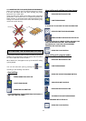
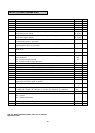
C.4.1.2.1 Service alarms not requiring service center
assistance
C.4 ALARMS
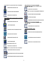
SYMBOL DESCRIPTION ACTION
b1
Condenser temperature
high
Clean condenser; check air
circulation around
condenser
b2
Door open Close door
b3
Memory full Reset HACCP alarms
b4
Power failure Check plug properly
inserted in power supply
socket;
Check electrical system