


76
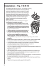
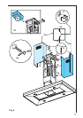
For extractor versions (13A), connect the other end of the exhaust pipe to the flue.
For filter versions (13F), fit deflector F to the support and secure it to the bracket
supplied using 4 screws, then connect the exhaust pipe to the connection ring located
on the deflector.
Fit the nuts with fixing hooks (14) supplied inside the top and bottom sections of
the flues at the rectangular slots. A total of 14 nuts must be fitted.
Fix the two bracket supplied with one screw each (15a)
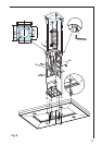
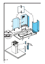
Join the two top sections of the flue to cover the support (15b) so that one of the
slots on the sections is situated on the same side of the control panel and the
other on the opposite side. Screw the two sections together with 8 screws and
springs (4 each side- see the plan diagram for joining the two sections - springs
must be fixed horizontally).
Fix the top flue assembly to the support, near the ceiling, with two screws (16 -
one each side).
Carry out electrical connection of control panel and bulbs (17).
Join the two bottom sections of the flue covering the support (18) using 6 screws
and springs (3 each side, see the plan diagram for joining the two sections -
springs must be fixed horizontally).
Insert the bottom section of the flue in its seat so that it completely covers the
motor compartment and electrical connection box, then ensure it from inside the
hood using two screws (19).
Apply the 2 tabs (20 - supplied) to cover the fixing points of the bottom flue
(CAUTION! THE BOTTOM FLUE TABS ARE THE NARROWER AND
SHALLOWER ONES).
The wider and deeper tabs are those used for the top flue, and must be cut to
size.
If necessary, slightly expand the tabs to ensure their adherence to the flue.
Turn the mains power on again at the central electrical panel and check for correct
hood operation.