


14
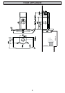
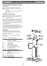
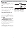
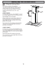
Fitting the Wall Brackets
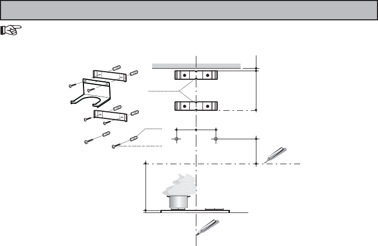
Wall marking:
• Draw a vertical line on the supporting wall up to the ceiling, or as high as practical, at the centre of the area
in which the hood will be installed.
• Draw a horizontal line at 650 mm above the hob.
• Place bracket 7.2.1 on the wall as shown about 1-2 mm from the ceiling or upper limit aligning the centre
(notch) with the vertical reference line.
• Mark the wall at the centres of the holes in the bracket.
• Place bracket 7.2.1 on the wall as shown at X mm below the fi rst bracket (X = height of the upper chimney
section supplied), aligning the centre (notch) with the vertical line.
• Mark the wall at the centres of the holes in the bracket.
• Mark a reference point as indicated at 116 mm from the vertical reference line and 310 mm above the horizontal
reference line.
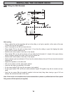
• Repeat this operation on the other side.
• Drill ø 8 mm holes at all the centre points marked.
• Insert the wall plugs (not supplied) in the holes.
• Fix the lower bracket 7.2.1 using the two screws (not supplied).
• Fix the upper bracket 7.2.1 and the air outlet connection support 7.3 together using the two screws (not sup-
plied).
• Insert the two screws 12a (not supplied) supplied in the hood body fi xing holes, leaving a gap of 5-6 mm
between the wall and the head of the screw.
Note: If the hood is to be installed onto a hollow construction or plaster or partition board wall then special
fi xing screws will be required (not supplied).
INSTALLING THE COOKER HOOD
11
12a
310
X
116
1÷2
116
650 min.
7.2.1