


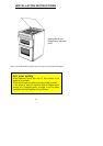


4. CONNECTING TO GAS
This appliance is designed to be installed with an appliance
flexible connection only. Supply piping should not be less
that R³/8. Connection is made to the Rc ½ (½" B.S.P.)
female threaded entry pipe located just below the hotplate
level on the rear left hand side of the appliance. NOTE:
ONLY LIQUID SEALANTS TO BE USED WHEN INLET
GAS PIPE IS FITTED TO RESET VALVE I.E.: DO NOT
USE P.T.F.E. SEALANT TAPE.
Check for gas soundness after connecting the gas supply.
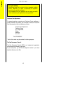
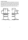
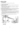
The gas bayonet connector must be fitted in the shaded
area indicated in Fig.3. Take into account that it must be
possible to pull the appliance forward sufficiently. The hose
must not get caught on the stability bracket.
IMPORTANT: FLEXIBLE TUBING USED MUST
COMPLY WITH BS. 669 CURRENT EDITION.
L.P.G. FLEXIBLE CONNECTIONS MUST BE OF A TYPE
SUITABLE FOR L.P.G. AND CAPABLE OF OPERATION
UP TO 50 mbar AND TO CARRY A RED STRIPE, BAND
OR LABEL.
5. CONNECTION TO THE ELECTRICITY
SUPPLY
WARNING: THIS APPLIANCE MUST BE EARTHED. DO
NOT EARTH THIS APPLIANCE TO THE GAS SUPPLY
PIPING.
This appliance must be connected to 230V-240V A.C. 50Hz
supply. It is supplied with 2 metres of 5 amp 3 core cable
incorporating a moulded 13 amp plug , fitted with a 3 amp
fuse, which can be plugged directly into the nearest suitable
socket. Ensure the plug is accessible to the user. If this is
not long enough, the supply cable can be replaced totally by
a longer cable at least 0.75mm² nominal cross sectional
area (24/0.2mm).
IF THE MOULDED PLUG IS CUT FROM THE CABLE
FOR ANY REASON, IT MUST BE DESTROYED OR
DISPOSED OF SAFELY, AS THE PROTRUDING WIRES
WILL BE AN ELECTRIC SHOCK HAZARD.
If any other type of plug is used it should incorporate a 3
amp fuse in either the plug or adapter or at the distribution
board.
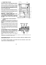
If the cable has to be threaded through small apertures in cabinets etc., it may be disconnected from the
appliance, then re-connected to as shown in Fig.4.
DO NOT EXTEND THE CABLE USING PLASTIC OR CERAMIC CONNECTION TERMINAL BLOCKS
AND/OR INSULATION TAPE.
ALL EXTERNAL WIRING BETWEEN THE APPLIANCE AND THE ELECTRICAL SUPPLY SHALL
COMPLY WITH I.E.E. WIRING REGULATIONS.
46
4
50
70
0
850
400
Fig.3
250
100
50
All dimensions in mm
Fig.4