


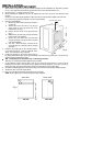
2. CONNECTION TO ELECTRICITY SUPPLY
WARNING: THIS APPLIANCE MUST BE EARTHED, DO NOT EARTH THIS APPLIANCE TO THE GAS
SUPPLY PIPING.
This appliance must be connected to a 230V-240V a.c. 50Hz supply which incorporates a 3 ampere fuse. If
any other type of plug is used it should incorporate a 5 ampere fuse in either the plug or adapter or at the
distribution board. The appliance is supplied with 2 meters (6.5 ft) of 5 ampere 3 core cable, fitted with a
moulded plug. If this proves insufficient to allow the appliance to be plugged into the nearest supply socket.
Ensure the plug is accesible to the user.
The supply cable can be either:-
i) Replaced totally by a longer cable at least 0.75mm²
nominal cross sectional area (24/0.2).
ii) Extended by using a B.E.A.B. approved 3-way sealed
flex connector with integral flex clamps.
DO NOT EXTEND THE CABLE USING PLASTIC OR
CERAMIC CONNECTION TERMINAL BLOCKS AND/OR
INSULATION TAPE.
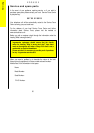
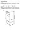
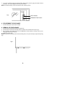
If the supply cable is replaced it is recommended that the
ends of the new cable all be cut to the same length 60mm,
any excess wire being stored inside the mains terminal see
Fig.5.
Should the supplied cable be required to be threaded through
small apertures in the cabinets it can be removed from the
mains inlet terminal block see Fig.5.
If the supplied plug is cut off dispose of it safely as it will be a
shock hazard if inserted into a 13 amp socket elsewhere in
the house.
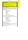
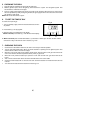
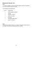
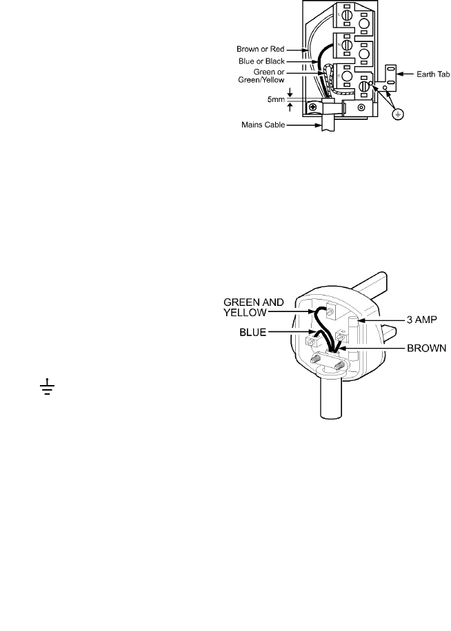
To fit a 3 pin 13 amp plug to the end of the appliance cable
(Fig.6). Connect the wires as follows:
BROWN to the live terminal.
BLUE to the neutral terminal.
GREEN and YELLOW to the earth terminal.
As the colours of the wires in the mains lead of this appliance
may not correspond with the coloured markings identifying
the terminals in your plug, proceed as follows:
The wire which is GREEN and YELLOW must be connected
to the terminal in the plug which is marked with the letter 'E'
or by the earth symbol or coloured GREEN or GREEN
and YELLOW.
The wire which is coloured BLUE must be connected to the
terminal which is marked with the letter 'N' or coloured black.
The wire which is coloured BROWN must be connected to
the terminal which is marked with the letter 'L' or coloured RED.
FIT A 3 AMP FUSE TO THE PLUG FUSE HOLDER
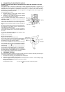
3. PRESSURE TESTING
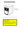
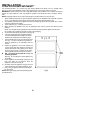
The pressure test point is located on the right hand side of the gas rail. Access to the test point is through a
cut out in the top right hand side of the control panel see Fig. 7.
1 Remove the hex head plug, turn anticlockwise from the test point.
2 Connect the pressure gauge to the test point.
3 Check the supply pressure by turning the oven thermostat to Mark 9. Then turn on the electricity supply.
Allow the oven burner to light and gas flow open up to full rate.
The pressure should be:-
For Natural Gas 20 mbar For L.P. Gas 28mbar for butane, 37mbar for propane.
38
Fig .5
Fig.6