


E
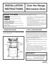
Installation Instructions
4
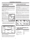
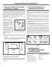
8 VENTILATION SYSTEM
(PREPARING OVEN FOR INSTALLATION)
This Over the Range Microwave Oven is designed for adaptation
to three types of hood ventilation systems. Select the type required
for your installation.
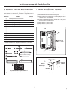
Recirculating — non-vented, ductless. Follow installation
procedure (A). Recirculating requires the use of the Charcoal
Filter, which has been installed in the oven.
Horizontal Exhaust — outside ventilation. Follow installation
procedure (B).
Vertical Exhaust — outside ventilation. Follow installation
procedure (C).
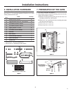
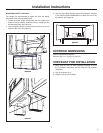
(A) RECIRCULATING: NON-VENTED, DUCTLESS OPERATION
The unit is shipped assembled for recirculating.
NOTE:
1. The Exhaust Damper Assembly is not required for recirculating
exhaust.
2. The Charcoal Filter should be replaced every 6 to 12 months,
depending on use.
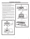
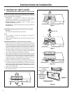
(B) HORIZONTAL EXHAUST: OUTSIDE VENTILATION
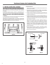
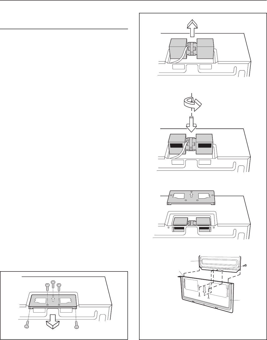
1. Remove 2 screws from back edge and 3 screws from the
top center of Fan Cover Bracket. Save 2 screws to be used
later and discard remaining 3. Remove Fan Cover Bracket
by sliding it in the opposite direction of the arrow on the Fan
Cover Bracket, as shown in Figure 7.
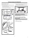
2. Lift Hood Fan Unit carefully and slip wires out of cavity. See
Figure 8. Caution: Do not pull or stretch hood fan wiring.
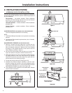
3. Rotate the Hood Fan Unit 180˚ so that the fan blade openings
are facing the back of the oven. See Figure 9 (A). Replace
Hood Fan Unit into the oven. Be careful not to pinch the wire
and the Hood Fan Unit. See Figure 9 (B).
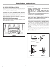
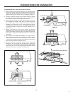
4. Put the wire back into the cavity. See Figure 10A.
5. Assemble the Exhaust Damper Assembly to the fan cover
bracket by sliding into the slits in the same directions as the
arrow. Use 1 Tapping Screw 4 x 12 mm from the INSTALLATION
HARDWARE and tighten into place. See Figure 10B.
6. This assembly will be mounted to the Outside Rear Exhaust
cutout in future instructions.
Figure 7
Figure 8
(B)
(A) Rotate 180˚
Figure 9
Figure 10A
Exhaust Damper
Assembly
Fan Cover Bracket
Apply Rear Cushion
after Exhaust
Damper Assembly
is screwed to wall.
Rear Cushion
Figure 10B
Save this assembly for
future instructions.