


- 7 -
GENERAL
Carefully read the following important information regarding
installation safety and maintenance. Keep this information
booklet accessible for further consultations.
The appliance has been designed for use in the ducting
version (air exhaust to the outside), filtering version (air
circulation on the inside).
SAFETY PRECAUTION
1. Take care when the cooker hood is operating
simultaneously with an open fireplace or burner that
depend on the air in the environment and are supplied by
other than electrical energy, as the cooker hood removes
the air from the environment which a burner or fireplace
need for combustion. The negative pressure in the
environment must not exceed 4Pa (4x10⁻⁵ bar). Provide
adequate ventilation in the environment for a safe
operation of the cooker hood.
Follow the local laws applicable for external air evacuation.
2. WARNING !
In certain circumstances electrical appliances may be
a danger hazard.
A) Do not check the status of the filters while the
cooker hood is operating
B) Do not touch the light bulbs after appliance use
C) Flambè cooking is prohibited underneath the cooker
hood
D) Avoid free flame, as it is damaging for the filters
and a fire hazard
E) Constantly check food frying to avoid that the
overheated oil may become a fire hazard
F) Disconnect the electrical plug prior to any
maintenance.
G) This appliance is not intended for use by young
children or infirm persons without supervision
H) Young children should be supervised to ensure they
do not play with the appliance
I) There shall be adequate ventilation of the room
when the rangehood is used at the same time as
appliances burning gas or other fuels
L) There is a risk of fire if cleaning is not carried out
in accordance with the instructions
INSTALLATION INSTRUCTIONS
• Electric Connection
The appliance has been manufactured as a class II,
therefore no earth cable is necessary.
The connection to the mains is carried out as follows:
BROWN = L line
BLUE = N neutral
If not provided, connect a plug for the electrical load
indicated on the description label. Where a plug is
provided, the cooker hood must be installed in order that
the plug is easily accessible.
An omnipolar switch with a minimum aperture of 3mm
between contacts, in line with the electrical load and
local standards, must be placed between the appliance
and the network in the case of direct connection to the
electrical network.
• The appliance must be installed at a minimum height of
650 mm from an cooker stove in case of a gashob or an
electrical hob.
If a connection tube composed of two parts is used, the
upper part must be placed outside the lower part.
Do not connect the cooker hood exhaust to the same
conductor used to circulate hot air or for evacuating
fumes from other appliances generated by other than an
electrical source.
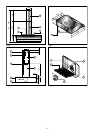
• MOUNTING OF THE HOOD IN THE LOWER PART OF AN
HANGING CUPBOARD
Drill 4 holes of 6 mm. diameter at the bottom of the hanging
cupboard as showed in the drawing fig.3.
Fit the hood in the cabinet with 4 screws, which are
appropriate to that kind of cupboard.
The appliance is provided with 2 air outlets, one which is
in the upper part and the other on the back. Both of them
can be used according to your requirements. A connecting
ring (C), which to join the connecting pipe to,and a cover
(A) to close the air outlet, which is not used, are supplied.
• MOUNTING OF THE HOOD IN THE WALL
Make 4 holes (B-P) according to the measurements
indicated in fig. 2.
For the various assembly operations, use screws and
anchors suitable for the type of wall (eg., concrete,
plasterboard, etc.)
Hang the hood on the wall using the two holes (B) fig. 2.
Secure the hood to the wall using the two lower safety holes
(P).
• MOUNTING OF THE HOOD ON THE WALL
Drill 2 holes on the wall, which correspond to the position
(B) of the drawing fig. 1.
Hang the hood on the 2 holes by using the screws and
dowels with expanding plug ,which are aprropriate for that
kind of wall (ex. concrete, plasterboard etc.)
Fix definitely the hood through the 2 security holes (Z).
• FITTING THE PIPES (OPTIONAL)
Make four holes (G-H) according to the measurements
indicated in fig. 2
For the various assembly operations, use screws and
anchors suitable for the type of wall (eg., concrete,
plasterboard, etc.)
Secure the bracket (Z) to the wall fig. 2
Position the two pipes vertically on the hood.
Hang the pipe fitting (F) using the 2 holes (H) fig. 2
Remove pipe fitting (E) from fitting (F) and secure to the
side of the bracket (Z) with the screws provided.
• FITTING THE GLASS SECTION (OPTIONAL)
Position the glass section complete with supports (V) as
indicated in fig. 1 and secure to the hood using the screws
provided.
ENGLISH
GB