


- 8 -
INSTALLATION INSTRUCTIONS
OPERATING INSTRUCTION
READ AND SAVE THESE INSTRUCTIONS
GENERAL
• Carefully read the following important information regarding installation safety and main-
tenance. Keep this information booklet accessible for further consultations.
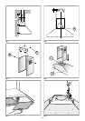
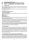
The appliance has been designed for use in the ducting version (air exhaust to the outside
– Fig.1).
INSTALLATION INSTRUCTIONS
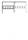
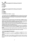
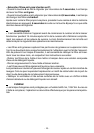
• Power Supply Connection
For connection to the power supply refer to the follows fig.6 :
BLACK = L line
WHITE = N neutral
GREEN / YELLOW = G ground
A double-pole switch properly rated must be installed to provide the range hood power
supply disconnection.
The appliance must be installed at a minimum height of 26 inches (66 cm) from an electric
cooker stove, or 30 inches (76 cm) from gas or combined cooker stoves. If a connection
ductwork composed of two parts is used, the upper part must be placed outside the lower
part. Do not connect the range hood exhaust duct air to the same duct air used to exhaust
hot air or fumes from other appliances other than electrical. Before proceeding with the
assembly operations, remove the anti-grease filter(s) (Fig.5) so that the unit is easier to
handle.
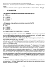
• FIXING TO THE WALL
Drill the holes A respecting the distances indicated (Fig.2). Fix the appliance to the
wall and align it in horizontal position to the wall units. When the appliance has been
adjusted, definitely fix the hood using the screws A (Fig.4). For the various installa-
tions use screws and screw anchors suited to the type of wall (e.g. reinforced con-
crete, plasterboard, etc.). If the screws and screw anchors are provided with the
product, check that they are suitable for the type of wall on which the hood is to be
fixed.
• FIXING THE DECORATIVE TELESCOPIC FLUE
Arrange the electrical power supply within the dimensions of the decorative flue.
Prepare the air exhaust opening. Adjust the width of the support bracket of the upper
flue (Fig.3). Then fix it to the ceiling using the screws A (Fig.3) in such a way that it
is in line with your hood and respecting the distance from the ceiling indicated in
Fig.2. Connect the flange C to the air exhaust hole using a connection pipe (Fig.4).
Insert the upper flue into the lower flue and rest above the frame. Extract the upper
flue up to the bracket and fix it with the screws B (Fig.3).