


97565C (Rev. J - 8/07)
EDFP210FP*B EDFP214FP*B EDFP217FP*B
PAGE 7
The freeze resistant package must be mounted on an interior wall in a heated area. The room temperature of the interior
heated area must be 50° F (10° C) or higher. The freeze resistant package may be surface or recessed mounted. If recess
mounted the surface of the cover must be flush with the interior wall surface. The package is furnished with screws for
mounting the cover to the box. If the box is recess mounted, do not fasten the top and bottom of the cover to the box. Use
the holes on the front only.
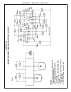
1. Assemble the operating cable to the fountain bracket. (Fountain should be mounted to exterior wall) Create a loop in
the cable and thread the free end of the cable through the wall into the freeze resistant box. The adjustment nuts should
be in the middle of threaded area on the operating cable. See Figure 9
2. Connect free end of operating cable to the valve-operating bracket. The end of the cables must be recessed into the
indents on the pivot brackets.
3. Remove cable free play by adjusting the jam nuts on the ends of the operating cable. See Figure 6
4. Connect water line from fountain bubbler into freeze resistant box. The connection to the box uses a quick connect
water fitting. Position the water line, in the fountain, to drain back into interior mounted box. Any water left standing, in
the exterior line, can freeze.
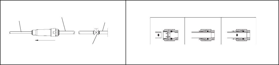
To insert tubing, push tube straight into fitting until it reaches a positive stop. To remove tubing from the fittings, relieve
water pressure, push in on dark gray collar while pulling out on the tubing. See Figure 11
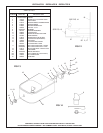
5. Connect drain and water supply lines to the freeze resistant fountain. Refer to Figure 1 for component positions. Inline
strainer must be used on the inlet water line.
Start-up
1. Turn on building water supply and check all connections for leaks. Repair as required.
2. Stream height is factory set at 35 PSI. If stream height needs to be changed adjust the regulator in the freeze resistant
package. Clockwise adjustment raises stream height, counter clockwise adjustment will lower stream.
3. Adjust operating cable as required. Cable system should have a minimal amount of free play to allow for proper valve
operation. If the system is too tight the valve will stay in the on position creating constant water flow. Too much free
play will result in non-operation of the valve with the push-buttons.
4. Note: Water from the drain back tube in the freeze resistant package, will continue to run while the valve is actuated.
5. After cable system is adjusted properly stuff flexible insulation into any openings between the outside wall and the
interior box.
6. Recheck all connections. If all connections are leak free replace cover(s) on the freeze resistant box(es) and fountain(s).
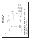
FIG. 10
NOTE: WATER FLOW DIRECTION
BUILDING WATER
INLET
SERVICE STOP
(NOT FURNISHED)
1/4" O.D. TUBE
WATER INLET
3/8" O.D. UNPLATED
COPPER TUBE CONNECT
COLD WATER SUPPLY
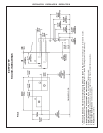
TUBE IS
SECURED
IN POSITION
SIMPLY PUSH IN
TUBE TO ATTACH
PUSH IN COLLET
TO RELEASE TUBE
PUSHING TUBE IN BEFORE
PULLING IT OUT HELPS TO
RELEASE TUBE
FIG. 11
OPERATION OF QUICK CONNECT FITTINGS