


6
Lock Panel (LP)
The keypad can be locked to prevent unwanted tampering
with the control settings. In the User Menu, change the menu
item LP selection to On. When the menu is exited and set-
tings are stored, the
or , and keys will be disabled
from normal use.
To unlock the keypad, press and hold
for 5 seconds.
The display will change to show LP On. Momentarily press
or to change to Off and then momentarily press .
The control will return to normal operation and the keypad
will be unlocked.
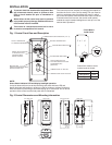
Binary Input (bIn) and Set Back (Sb)
Binary Input is an option to allow the setpoint temperature
to set back to conserve energy or for other reasons as
determined by the user. Set Back determines the number of
degrees the setpoint temperature will be changed.
An external switch or N.O. relay can be connected to the BIN
and GND terminals of the control. With bIn set to On, when
the switch is closed, the control will change the setpoint tem-
perature by the number of degrees set in Sb. In Heat mode,
setpoint temperature will change lower or cooler. In Cool
mode, setpoint temperature will change higher or warmer.
During the time that the switch is closed, bIn will appear in
the lower left corner of the display. If an alarm is connected
be sure that the alarm delay time is set long enough to allow
for the temperature change to avoid a “false” alarm.
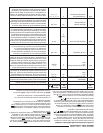
Alarm (AL)
This control has an alarm relay that will provide an output to
alert of a malfunction. The alarm relay output must be con-
nected to an external light, audible alarm or other device as
needed by the user. If AL is set to 0, the alarm relay will not
provide any alarm output. If AL is set to a value greater than
0, the alarm relay output provides indication of three error
conditions: Temperature Out of Range, Power Loss and Sen-
sor Operation Failure. Although AL must be set to a value
greater than 0 for any alarm output to be provided, the value
selected is the time delay, in minutes, before a Temperature
Out of Range alarm is set. The alarm time delay does not
apply to Power Loss or Sensor Operation Failure.
OPERATION
Temperature out of range – If the temperature is more than
5° from the setpoint, continuously for the length of time set in
AL, the alarm relay output will close. The delay should be set
to allow for conditions that will cause the temperature to vary,
such as defrost cycle, opening door for stock removal or
replacement or Set Back changes. When setting the AL time,
consideration should be given to these events to prevent a
false alarm.
If the control set back feature is used to change the setpoint,
the delay period set in AL should consider the time it takes
for the system to reach the set back temperature to avoid a
false alarm.
Power Loss – If the temperature control experiences an input
power failure, the control will close the alarm relay before
total power of the control is lost. The delay time is not used in
this event, and the alarm relay will close within seconds of a
power failure. In addition, the load relay contact change state
per the Sensor Operation Failure (SOF) setting.
When power returns, the alarm contacts will open. The load
relay will remain in the SOF position the length of time set in
Anti Short-Cycle Delay (ASd) after power resumption. The
display will blink the flame or snowflake icon for this time to
indicate the load is “locked” out. This is to help protect the
user’s equipment from damage by short cycle switching.
Sensor Operation Failure (SOF) – If in operation, the sen-
sor wiring should become open or shorted, the temperature
control will begin blinking SOF with SH for shorted or SO for
sensor open. However, the control will wait approximately
1 minute before closing the alarm output relay - indicating
sensor operation failure. If during the 1 minute, the sensor
“resumes” normal operation, the time is reset and the control
returns to normal display. The load relay will operate as se-
lected in sensor operation failure (SOF).
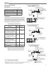
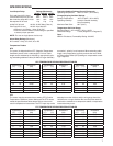
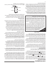
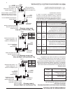
Multiple Sensors
The 16E09 is normally operated with one sensor. If an aver-
age temperature of an area is required, 4 sensors may be
used and wired in the method shown below. If 4 sensors are
used, they must all be of the same model.
NOTE: When using multiple sensors, 4 sensors must be
used. The control will not operate with 2 or 3 sensors.
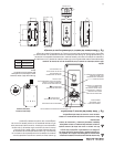
Using the Alarm Output and power
stealing in combination – When using
power stealing mode and the alarm output, it is
important for the installer to review the wiring circuit
of the installation to insure no device is present that could
interrupt electrical power to the temperature control. Such
a device could be a defrost timer, as one example, that may
be used in some refrigeration applications.
If a device is in the system wiring that can periodically
disrupt power to the load and the temperature control,
the power stealing mode of the control cannot be used. A
neutral wire must be connected to the control and select
the non power stealing mode for the control. This keeps
power to the control during power interruptions to the load
and avoids a “false” alarm output.
SPECIAL
NOTE
Sensor 3
Sensor 4
Sensor 1
Sensor 2