


11
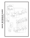
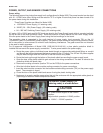
Sensor wiring to signal boards
Wire the correct sensor leads to the measurement board using the lead locations marked directly on the board.
After wiring the sensor leads to the signal board, carefully slide the wired board fully into the enclosure slot and
take up the excess sensor cable through the cable gland.
For best EMI/RFI protection use shielded output signal cable enclosed in an earth-grounded metal conduit.
Connect the shield to earth ground. AC wiring should be 14 gauge or greater. Provide a switch or breaker to dis-
connect the analyzer from the main power supply. Install the switch or breaker near the analyzer and label it as
the disconnecting device for the analyzer.
Keep sensor and output signal wiring separate from power wiring. Do not run sensor and power wiring in the same
conduit or close together in a cable tray.
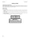
Electrical installation must be in accordance with
the National Electrical Code (ANSI/NFPA-70)
and/or any other applicable national or local codes.
WARNING
RISK OF ELECTRICAL SHOCK
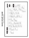
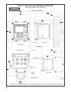
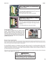
MODEL 1056 WIRING
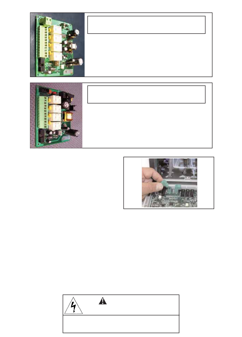
This power supply automatically detects DC power and
accepts 20VDC to 30VDC inputs.
Four programmable alarm relays are included.
This power supply automatically detects AC line condi-
tions and switches to the proper line voltage and line
frequency.
Four programmable alarm relays are included.
Switching AC Power Supply (-03 ordering
code) is shown below:
24VDC Power Supply (-02 ordering code)
is shown below:
Current Output wiring
All instruments are shipped with two 4-20mA current
outputs. Wiring locations for the outputs are on the
Main board which is mounted on the hinged door of the
instrument. Wire the output leads to the correct posi-
tion on the Main board using the lead markings (+/positive,
-/negative) on the board. Male mating connectors are
provided with each unit.