


5
SPECIFICATIONS - General
Enclosure: Polycarbonate. NEMA 4X/CSA 4 (IP65).
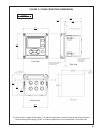
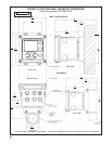
Dimensions: Overall 155 x 155 x 131mm (6.10 x 6.10
x 5.15 in.). Cutout: 1/2 DIN 139mm x 139mm (5.45 x
5.45 in.)
Conduit Openings: Accepts 1/2” or PG13.5 conduit
fittings
Display: Monochromatic graphic liquid crystal display.
128 x 96 pixel display resolution. Backlit. Active
display area: 58 x 78mm (2.3 x 3.0 in.).
Ambient Temperature and Humidity: 0 to 55°C
(32 to 131°F). Turbidity only: 0 to 50°C (32 to
122°F), RH 5 to 95% (non-condensing)
Storage Temperature Effect: -20 to 60ºC (-4 to 140°F)
Power: Code -01: 115 VAC ±15% 60 Hz ±6%, 10W;
230 VAC ±15% 50 Hz ±6%, 10 W.
Code -02: 20 to 30 VDC. 15 W.
Code -03: 84 to 265 VAC, 47 to 63.0 Hz. 15 W.
Note: Code -02 and -03 power supplies include four
programmable relays
Equipment protected by double insulation
Alarms relays*: Four alarm relays for process meas-
urement(s) or temperature. Any relay can be config-
ured as a fault alarm instead of a process alarm. Each
relay can be configured independently and each can
be programmed with interval timer settings.
Relays: Form C, SPDT, epoxy sealed
Inductive load: 1/8 HP motor (max.), 40 VAC
Maximum screw torque for power lead connector and
relay terminal blocks is 0.6 N
.
m
*Relays only available with -02 power supply (20 - 30 VDC) or -03
switching power supply (84 - 265 VAC)
Inputs: One or two isolated sensor inputs
Outputs: Two 4-20 mA or 0-20 mA isolated current out-
puts. Fully scalable. Max Load: 550 Ohm. Output 1
has superimposed HART signal (configurations
1056-0X-2X-3X-HT only)
Current Output Accuracy: ±0.05 mA @ 25 ºC
Terminal Connections Rating: Power connector
(3-leads): 18-12 AWG wire size. Signal board ter-
minal blocks: 26-16 AWG wire size. Current output
connectors (2-leads): 24-16 AWG wire size. Alarm
relay terminal blocks: 18-16 AWG wire size
(-02 24 VDC power supply and -03 84-265VAC
power supply)
Weight/Shipping Weight: (rounded up to nearest lb or
nearest 0.5 kg): 3 lbs/4 lbs (1.5 kg/2.0 kg)
RFI/EMI: EN-61326
LVD: EN-61010-1
Hazardous Location Approvals -
Class I, Division 2, Groups A, B, C, & D
Class Il, Division 2, Groups E, F, & G
Class Ill T4A Tamb= 50
°C
Evaluated to the ANSI/UL Standards. The ‘C’ and ‘US’ indicators
adjacent to the CSA Mark signify that the product has been evaluated
to the applicable CSA and ANSI/UL Standards, for use in Canada
and the U.S. respectively
Options for CSA: -01, 02, 03, 20, 21, 22, 24, 25, 26,
27, 30, 31, 32, 34, 35, 36, 37, 38, AN, and HT.
Note: Turbidity configurations (Models 1056-02-27-38-
AN/-HT, 1056-03-27-38-AN/-HT, 1056-02-27-37-AN/
-HT and 1056-03-27-37-AN/-HT) are CSA approved
Class I Div. 2 for hazardous area installation.
Class I, Division 2, Groups A, B, C, & D
Class Il & lll, Division 2, Groups E, F, & G
T4A Tamb= 50
°C Enclosure Type 4X
CAUTION
RISK OF ELECTRICAL SHOCK
Maximum Relay Current
Resistive
28 VDC 5.0 A
115 VAC 5.0 A
230 VAC 5.0 A
POLLUTION DEGREE 2: Normally only non-conductive
pollution occurs. Occasionally, however, a temporary
conductivity caused by condensation must be expected.
Altitude: for use up to 2000 meter (6562 ft.)
WARNING
Exposure to some chemicals may degrade the
sealing properties used in the following devices:
Zettler Relays (K1-K4) PN AZ8-1CH-12DSEA
WARNING
Options for FM: -01, 02, 03, 20, 21, 22, 24, 25, 26, 27,
30, 31, 32, 34, 35, 36, 37, 38, AN, and HT.
Note: Turbidity configurations (Models 1056-02-27-38-
AN/-HT, 1056-03-27-38-AN/-HT, 1056-02-27-37-AN/-
HT and 1056-03-27-37-AN/-HT) are FM approved
Class I Div. 2 for hazardous area installation.
Ordinary Locations-
The following ordering options are approved by UL: -01,
02, 03, 20, 21, 22, 23, 24, 25, 26, 27, 30, 31, 32, 33,
34, 35, 36, 37, 38, AN, DP, and HT.
Note: -UL order code must be specified for UL approval.
Model 1056 UL configurations are assembled per
UL requirements and are marked UL on the unit.