


Page 14 15627-5-0807
Before operating this heater, please review the safety warnings
pages at the beginning of this manual and those precautions and
warnings listed below.
1. Know what type of ignition system this model has (standing
pilot) and follow the applicable SAFETY and LIGHTING
instructions.
2. Check to ensure there are no gas leaks. If you are unsure,
turn gas off to the heater and call a service person or your gas
utility.
CAUTION: Clothing or other flammable material should not
be placed on or near the appliance.
WARNING: Children and adults should be alerted to the
hazard of high surface temperature and should stay away
to avoid burns or clothing ignition. Young children should
be carefully supervised when they are in the same room
as the appliance.
3. Tampering is DANGEROUS and voids all warranties. Any
component that is found to be faulty, must be replaced with
an approved component.
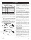
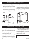
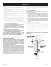
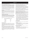
Initial Lighting (Figure 14)
Upon completing the gas line or turning the gas valve "ON" after it
has been in the "OFF" position, a small amount of air will be in the
lines. When first lighting the appliance, it will take a few minutes
for the lines to purge themselves of this air. Once the purging is
complete, the appliance will light and operate satisfactorily.
Subsequent lightings of the appliance will not require such purging
if the gas valve is not turned to "OFF."
Standing Pilot Operation
1. Follow the SAFETY and LIGHTING INSTRUCTIONS for
standing pilot controls found in this manual and on labels found
attached to the appliance.
CAUTION: During the initial purging and subsequent
lightings, never allow the gas valve control knob to remain
depressed in the "pilot" position without pushing the piezo
ignitor button at least once every second.
2. During the heating season, leave the control valve knob in the
"ON" position. This will allow the pilot flame to remain lit.
Turn the burner flame on or off with the appliance ON/OFF
rocker switch, wall switch, remote control kits or 750 millivolt
wall thermostat.
NOTE: The gas control valve allows you to increase or decrease the
height of the main burner flame. The control valve has a pressure
regulator with a knob as shown in Figure 14. Rotate the knob
clockwise to "HI" to increase the flame height and counterclockwise
to "LO" to decrease the flame height.
3. When the heating season is over, turn the on/off switch to
"OFF" and the control valve to "OFF". The system, including
the pilot light, will be shut down.
Figure 14
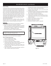
Maximum and Minimum Input
The gas valve on the appliance allows the input to adjust between
a maximum input of 30,000 to a minimum input of 21,000 Btuh.
Please be advised, the maximum input provides the greatest amount
of yellow flame and ember glow on the log set. The minimum
input substantially decreases the yellow flame and ember glow
on the log set.
This heater must be properly connected to a venting system. This
heater is equipped with a vent safety shutoff system.
Warning:
Operation of this heater, when not connected to a properly
installed and maintained venting system or tampering
with the vent safety shutoff system, can result in carbon
monoxide (CO) poisoning and possible death.
This appliance needs fresh air for safe operation and must be
installed so there are provisions for adequate combustion and
ventilation air.
This fireplace heater is equipped with a vent safety switch. The
vent safety switch will cause gas flow to the pilot to "shut off"
due to improper venting or a blocked flue.
If the vent safety switch continues to "shut off" the gas flow to
the pilot a qualified service person must be contacted to inspect
for improper venting, blockage in the vent pipe or the vent safety
switch for being defective.
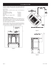
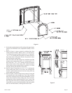
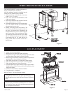
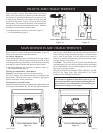
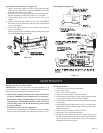
Reversible Vertical or Horizontal Draft Diverter
This fireplace heater has a reversible draft diverter. The draft
diverter is installed in the vertical position at the factory. Please
use the following steps to change the draft diverter from the vertical
position to the horizontal position.
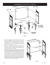
1. Remove (8) hex-head screws located adjacent to the flue collar
on the draft diverter.
2. Rotate flue collar to the horizontal position on the draft
diverter.
3. Attach flue collar to draft diverter with (8) hex-head screws from
Step 1.
OPERATING GUIDELINES
VENT SAFETY SHUTOFF SYSTEM