


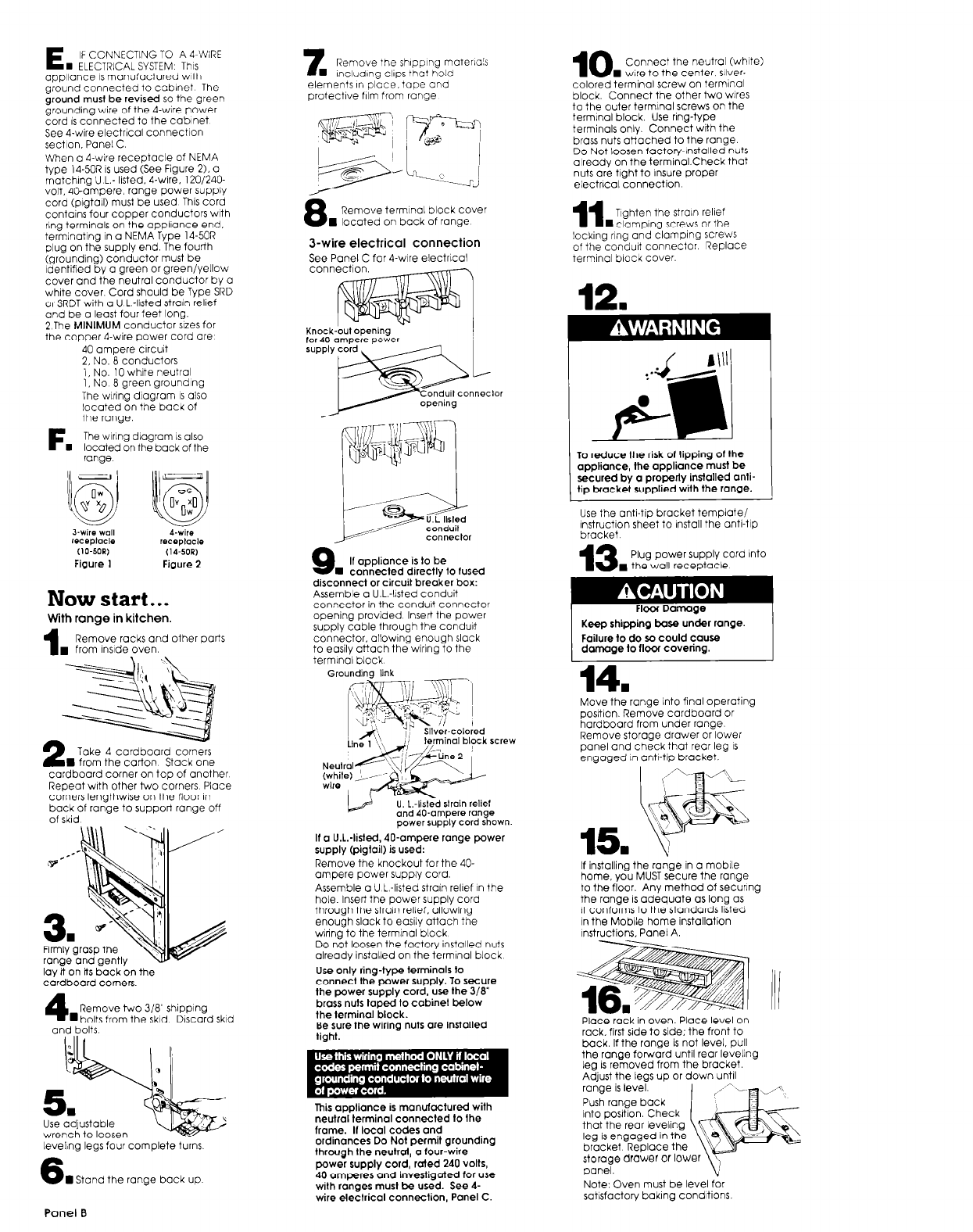
E
IF CONNECTING TO A d-WIRE
n ELECTRICAL SYSTEM This
aool~once IS manufactured with
Q&nd connected to cabinet The
ground musi be revised so the
green
grounding wire of the 4-wire power
cord IS connected to the cabinet
See 4.wire electrical connectIon
sectlon. Panel C.
7
Remove the shIppIng moterla!s
n IncludlnQ Clips that hold
elements in place, tape and
protective film from range
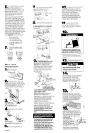
10
Connect the neutral (white)
n wire to the center. sliver-
colored terminal screw on termlnol
block. Connect the other two wires
to the outer termlnol screws on the
terminal block. Use ring-type
terminals only. Connect with the
brass nuts atiached to the range.
DO Not loosen factory-installed nuts
already on the terminol.Check that
nuts are tight to insure proper
electrlcal connection
8
Remove terminal block cover
8 located on back of range
11
TIghten the strain relief
n clamping screws or the
J-wire electrical connection
See Panel C for 4-wire electrical
locking
rlnQ and clamping screws
of the conduit connector. Replace
terminal block cover.
When o 4-wire receptacle of NEMA
type 14.50R is used (See Figure 2). 0
matching U L.- listed. 4-wire. 120/240-
volt, 4sampere. range power supply
cord (pigtall) must be used This cord
contains four copper conductors with
ring terminals on the oppllonce end.
termlnatlna in a NEMA Tvpe 14.50R
$ug on the supply end.(ihe fourth
(grounding) conductor must be
Identified by 0 green or green/yellOW
cover and the neutral conductor by 0
white cover. Cord should be Type SRD
or SRDT with a U L -lIsted strain relief
and be o least four feet long.
2
The
MINIMUM
conductor SlZeS for
the copper 4-wire power cord are
\
12
n
Knock-out opening
for AO-ampere power
,
nneclor
40 ampere circuit
2, No. 8 conductors
1, No. 10 white neutral
1, No 0 Qreen grounding
The wring
dl0QrOm IS
also
located on the back of
the range.
The wlrlng diagram IS also
located on the back of the
range
F.
To reduce the risk 01 tipping of the
appliance, the appliance must be
secured by a properly installed anti-
tip bracket supplied with the range.
connector
Use the anti-tip bracket template/
Instruction sheet to install the anti-tip
bracket.
13
Plug power supply cord Into
. the wall receptacle
A-wire
receplaclo
(14.SOP,
Figure 2
9
If appliance is to be
n
connected directly to fused
disconnect or circuit breaker box:
Assemble o U.L.-llsted conduit
connector in the conduit connector
opening provided Insert the power
supply cable through the conduit
connector, ollowlng enough slack
to easily attach the wiring to the
termlnol block
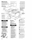
Now start.. .
Floor Damage
Keep shipping base under range.
Failure to do so could cause
damage to flwr coveting.
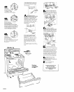
With range in kitchen.
1
Remove racks and other ports
. from InsIde oven.
14.
Grounding link
power supply cord shown.
Move the range Into final operating
posrtlon. Remove cardboard or
hardboord from under range.
Remove storage drawer or lower
panel and check that rear leg IS
engaged I” anti-tip bracket.
Take 4 cardboard corners
n from the carton Stack one
cardboard corner on top of another
Reoeat with other two corners Place
comers lengthwlse on the floor In
back of ronQe to support
range off
15.
If a U.1:listed, 40-ampere range power
supply (pigtail) is used:
Remove the knockout for the 40.
ampere power supply cord.
Assemble o U L-listed strain relief I” the
hole. Insert the power SUDDIV cord
through the strain relief. bl’lowing
enough slack to easily attach the
wiring to the terminal block
Do not loosen the factory installed nuts
already installed on the termlnol block
Use only ring-type terminals to
connect the power supply. To secure
the power supply cord, use the 3/a”
brass nuts taped to cabinet below
the terminal block.
Be sure the wiring nuts are installed
tight.
If
installing the range in a mobile
home, you MUST secure the range
to the floor. Any method of securing
the range IS adequate OS long as
It conforms to the standards listed
in the Mobile home installation
Instructions. Panel A.
lay it on Its back on the
cardboard corners
4
Remove two 318” shipping
n bolts from the skid Discard skid
Place rack in oven. Place level on
rack. first side to side; the front to
back. If the range is not level, pull
the range forward until rear leveling
leg 1s removed from the bracket.
Adiust the leas up or down until
and bolts
range is levei
Push range back
into posItIon. Check
that the rear leveling
leg is engaged in the
bracket Replace the
This appliance is manufactured with
neutral terminal connected to the
frame. If local codes and
ordinances Do Not permit grounding
through Ihe neutroi, o four-wire
power supply cord, raied 240 volts,
40 amperes and invesligated for use
wilh ranges must be used. See 4-
wire electrical connection, Panel C.
Use adjustable
wrench to loosen
leveling legs four complete turns.
6
n Stand the range back up
storage drawer or lower \y
panel.
v
Note: Oven must be level for
satisfactory baking conditions
Panel B