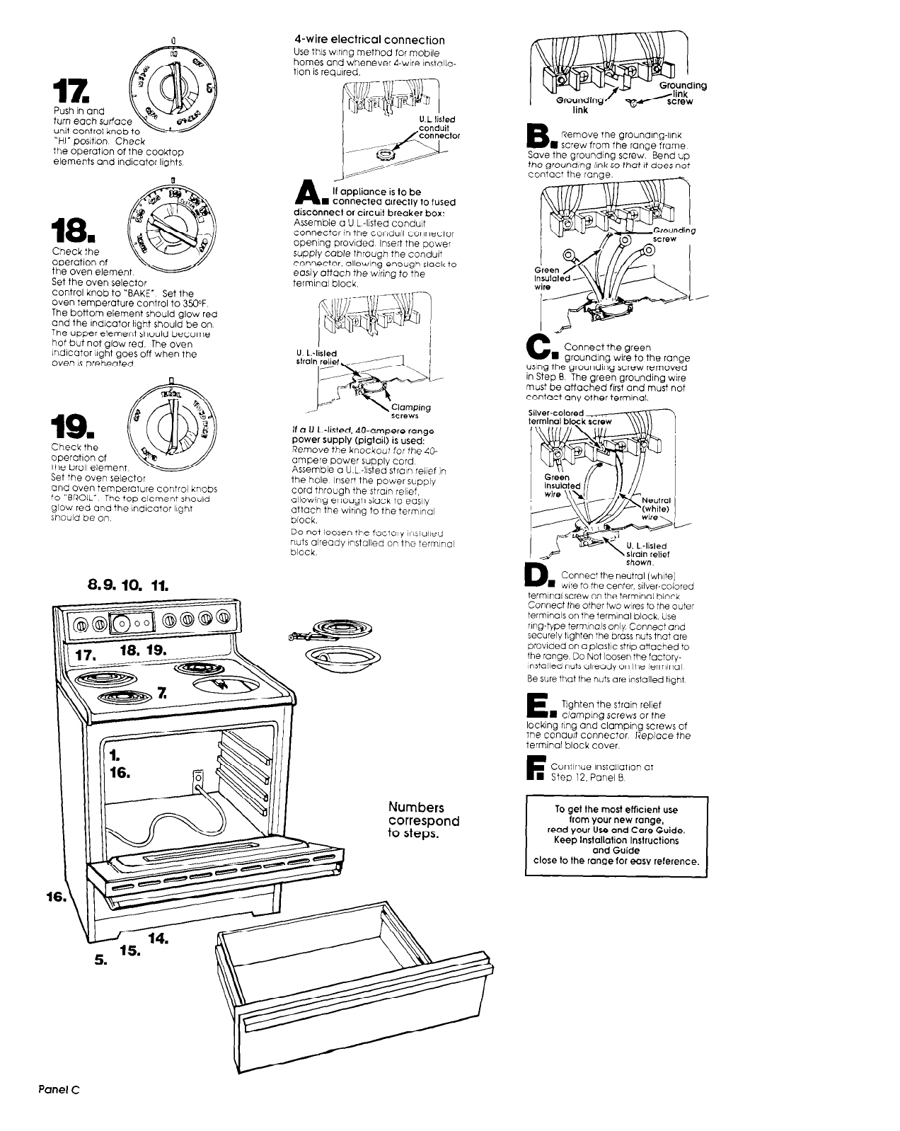
turn
each surfa
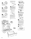
“HI- postion Check
the operation of the cooktop
elements and Indicator lights
18
n
Check the
operation of
the oven element
Set the oven selector
control knob to “BAKE.
Set the
oven temperature control to 35ooF.
The bottom element should glow red
and the lndlcator light should be on
The upper element should become
hot but not glow red. The oven
Indicator light goes off when the
Oven is preheated.
19.
Check the
operotlon of
the broil element
Set the oven selector
and oven temperature control knobs
to “BROIL- The top element should
glow red and the ndlcator light
should be on
8.9. 10. 11.
4-wire electrical connection
Use this wlrlng method for moblle
homes and whenever 4-wire Installa-
tlon is reaulred.
A
II appliance is lo be
W connected direcilv to fused
disconnect or circuit break& box:
Assemble a U L -Ilsted conduit
connector in the condut connector
OPenIng provided Insert the power
supply cable through the conduct
COnneCtOr. allowIng enough slack to
eC%ly attach the wiring to the
terminal block
screws
If a U-L.-listed, 40.ampere range
Power SUPplY (Pigtail) iS used:
Remove the knockout for the SO-
ampere Power supply cord
Assemble o U.L -lIsted stroln relief in
the hole Insert the power supply
cord through the strain relief,
allowing enough slack to easily
attach the wiring to the terminal
block.
Do not loosen the factory Instolled
nuts already Instolled on the termlnol
block
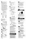
correspond
to steps.
Numbers
ing
B
Remove the grounding-llnk
l screw from the range frame
Save the grounding screw. Bend up
the grounding link so that It does not
4
C
n
Connect the green
grounding wire to the range
using the grounding screw removed
in Step B The green grounding wire
must be attached first and must not
Contact any other terminal.
‘b
D
w
Connect the neutral (white)
wire to the center. silver-colored
terminal screw on the terminal block
Connect the other iwo wares to the outer
termlnals on the terminal block. Use
ring-type termlnols only Connect and
securely llghten the brass nuts thot are
provided on a plostlc strip attached to
the range Do Not loosen the foctory-
Installed nuls already on the terminal
Be sure that the nuts are installed tight
E
Tighten the strain relief
H clamplng screws or the
locking ring and clamping screws of
the con&It connector Replace the
terminal block cover.
F
Continue lnstallatlon at
n Step 12. Panel B
I
To gel the most etticient use
from Your new ranae.
read your iJse and Care&de.
Keep
Installation Instructions
and Guide
close
to the range for easy reference.
Panel C


