


Version 03/08- Page 7
3. Remove the cover from the eld wiring compartment. Remove
the wiring electrical knockout using a at-blade screwdriver. Feed
the Power Supply Cable through the electrical knockout.
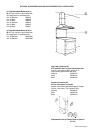
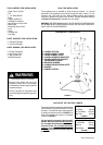
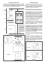
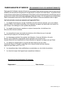
4. Hang the canopy on the brackets (1 in FIGURE 8). There are
two rectangular holes on the rear of the canpoy. The brackets
pass through these holes and the canopy hangs from the anges
on the brackets. Due to the weight of the canopy, two people
should lift it to avoid injuries. Make sure that the canopy is
secure on the brackets before releasing.
5. Level the canopy. The height and level of the canopy can
be adjusted by rotating the adjustment screws (W in FIGURE
8) on each side of the blower inside the rangehood.
INSTALL THE RANGEHOOD
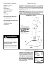
1. Remove the unit from the carton and place on a at surface
for assembly. Cover the surface to prevent accidental dam-
age. Remove all parts including the mounting hardware before
discarding the carton.
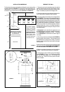
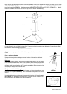
2. Remove the grease lters from the unit and set aside. The
grease lters are removed by pressing the handle in front of the
lter (FIGURE 7). When replacing, make sure that the lters are
properly positioned with the handles in front and visible.
6. Connect the Power Supply Cable to the rangehood. Attach
the White lead of the power supply to the White lead of the
rangehood with a twist-on type wire connector. Attach the Black
lead of the power supply to the Black lead of the rangehood with
a twist-on type wire connector. Connect the Green (Green and
Yellow) ground wire under the Green grounding screw.
7. Replace the eld wiring compartment cover and the grease
lters.
8. For ducted installations, the damper must be attached to the
exhaust opening on the top of the canopy. Connect the ductwork
and seal all connections with duct tape.
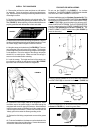
FOR DUCTLESS INSTALLATIONS
Do not use the DAMPER (I In FIGURE 1) for ductless
installations. The UPPER CHIMNEY COVER must be installed
rst, before the LOWER CHIMNEY DUCTLESS.
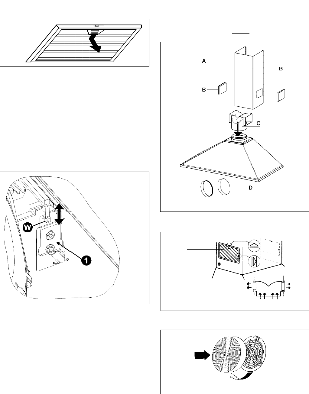
Ductless installations require a Ductless Conversion Kit. This
kit consists of a LOWER CHIMNEY DUCTLESS (A in FIGURE
9) with holes for the exhaust air, a DUCTLESS DIVERTER (C),
two VENT GRIDS (B) to cover the holes in the chimney cover,
and two CHARCOAL FILTERS (D). The DUCTLESS DIVERTER
must be installed before the LOWER CHIMNEY DUCTLESS
is attached (as indicated by the arrow in FIGURE 9). The
LOWER CHIMNEY COVER without holes (B in FIGURE 1)
should be discarded.
FIGURE 9
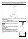
Once the LOWER CHIMNEY DUCTLESS with holes is installed,
the VENT GRIDS (B) are inserted into the holes (FIGURE 10).
B
Attach the CHARCOAL FILTERS to both sides of the blower (as
indicated in FIGURE 11). Install the grease lters.
FIGURE 10
FIGURE 11
FIGURE 8
FIGURE 7