


Version 03/08- Page 9
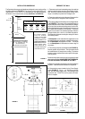
Rangehood Control Panel
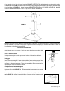
The control panel is located in the middle under the canopy. The
position and function of each control button are noted below (FIG-
URE 13A FOR 3-SPEED 500 CFM MODELS, FIGURE 13B FOR
2-SPEED 280 CFM MODELS).
Light On/Off Button ( L )
On/Off switch for the halogen lights. Move the switch to "1" to turn
the light ON and to "0" to turn it OFF.
Blower On/Off Button ( M )
On/Off switch for the blower. Move the switch to "1" to turn the
blower ON and to "0" to turn it OFF.
Blower Speed Button ( V )
Speed control for blower. FOR 3-SPEED 500 CFM MODELS
(FIGURE 13A), move the switch to"1" for LOW speed, "2" for
MEDIUM speed and "3" for HIGH speed. FOR 2-SPEED 280 CFM
MODELS (FIGURE 13B), move the switch to"1" for LOW speed
and "2" for HIGH speed.
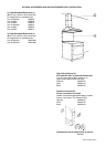
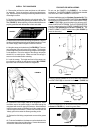
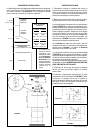
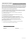
WIRING DIAGRAM FOR 3-SPEED 500 CFM MODEL
DIAGRAMME DE CÂBLAGE MODÈLE 3 VITESSE 500 PCM
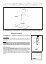
• This rangehood uses 20 watt Halogen Lamps. / Cette hotte utilise les ampoule halogènes de 20 W.
WIRING DIAGRAM FOR 2-SPEED 280 CFM MODEL
DIAGRAMME DE CÂBLAGE MODÈLE 2 VITESSE 280 PCM
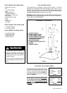
CONTROL PANELS AND WIRING DIAGRAMS
The Synthesis rangehood is available in two versions: a 3-speed 500
cfm version and a 2-speed 280 cfm version. Please check the speed
control under the canopy to note which version you own. The 3-speed
500 cfm version, will have options of speeds 1, 2, and 3. The 2-speed
280 cfm version, will only have options of speeds 1 and 2.
FIGURE 13A - 3-SPEED 500 CFM / 3 VITESSE 500 PCM FIGURE 13B - 2-SPEED 280 CFM / 2 VITESSE 280 PCM
PANNEAU DE COMMANDES & DIAGRAMMES DE CÂBLAGE
Le Synthesis est disponible dans deux versions : une version du
3 vitesse 500 pcm et une version du 2 vitesse 280 pcm. Veuillez
vérier la commande de vitesse sous la hotte pour noter quelle
version vous possédez. La version du 3 vitesse 500 pcm, aura des
options des vitesses 1, 2, et 3. La version du 2 vitesse 280 pcm,
aura seulement des options des vitesses 1 et 2.
Panneau de commandes
Le panneau de commandes est situé sur le moyen sous la hotte.
La position et la fonction de chaque bouton sont indiquées à la
FIGURE 13 (FIGURE 13A POUR MODÈLES 3-VITESSE 500 PCM,
FIGURE 13B POUR MODÈLES 2-VITESSE 280 PCM).
Bouton marche-arrêt de la lumière (L)
Interrupteur marche-arrêt pour la lumière. Régler à « 1 » pour mettre
en circuit (ON) et à « 0 » pour mettre hors circuit (OFF).
Bouton marche-arrêt du ventilateur (M)
Interrupteur marche-arrêt pour le ventilateur. Régler à « 1 » pour
mettre en circuit (ON) et à « 0 » pour mettre hors circuit (OFF).
Bouton de vitesse du ventilateur (V)
Commande de vitesse variable. POUR MODÈLES 3-VITESSE
500 PCM (FIGURE 13A), régler à « 1 » pour vitesse basse (LOW),
à « 2 » pour vitesse moyenne (MEDIUM) et à « 3 » pour vitesse
élevée (HIGH). POUR MODÈLES 2-VITESSE 280 PCM (FIGURE
13B), régler à « 1 » pour vitesse basse (LOW), et à « 3 » pour
vitesse élevée (HIGH).