


Version 03/08- Page 5
TOOLS NEEDED FOR INSTALLATION
• Saber Saw or Jig Saw
• Drill
• 1 1/4" Wood Drill Bit
• Pliers
• Phillips Screwdriver
• Flat Blade Screwdriver
• Wire Stripper or Utility Knife
• Metal Snips
• Measuring Tape or Ruler
• Level
• Pencil
• Caulking Gun
• Duct Tape
PARTS SUPPLIED FOR INSTALLATION
• 1 Hardware Package
• 1 Literature Package
PARTS NEEDED FOR INSTALLATION
• 2 Conduit Connectors
• Power Supply Cable
• 1 Wall or Roof Cap
• All Metal Ductwork
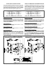
9 Feet Straight Duct
2 - 90˚ Elbows
Wall Cap
Total System
9.0 feet
10.0 feet
0.0 feet
19.0 feet
FIGURE 3
3.0 feet
5.0 feet
12.0 feet
0.0 feet
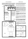
45˚ Elbow
90˚ Elbow
90˚ Flat Elbow
Wall Cap
FIGURE 2
CALCULATE THE DUCTRUN LENGTH
The ductrun should not exceed 35 equivalent feet
if ducted with the required minimum of 6" round
ductwork. Calculate the length of the ductwork
by adding the equivalent feet in FIGURE 2 for
each piece of duct in the system An example
is given in FIGURE 3.
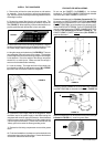
For best results, use no more than three 90°
elbows. Make sure that there is a minimum of
24" of straight duct between elbows if more
than one is used. Do not install two elbows
together. If you must elbow right away, do it
as far away from the hood's exhaust opening
as possible.
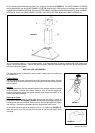
WARNING
Because of the weight and size of the
rangehood canopy, two or more people
are needed to move and safely install the
rangehood canopy.
Failure to properly lift rangehood could
result in damage to the product or personal
injury.
PERSONAL INJURY HAZARD
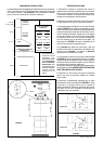
PLAN THE INSTALLATION
This rangehood can be installed as either ducted or ductless. In a ducted
application, this rangehood can be vented through the wall or ceiling. To vent
through a wall, a 90° elbow is used. When installed ductless, the rangehood
vents out of grates on the sides of the chimney. Ductless installations require
a Ductless Conversion Kit, available from your dealer.
WARNING! BEFORE MAKING ANY CUTS OR HOLES FOR INSTALLATION,
DETERMINE WHICH VENTING METHOD WILL BE USED AND CAREFULLY
CALCULATE ALL MEASUREMENTS.
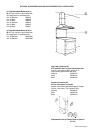
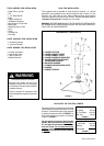
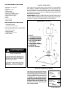
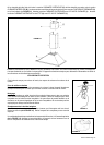
RANGEHOOD COMPONENTS
FIGURE 1
A. CANOPY SECTION
B. LOWER CHIMNEY COVER
C. UPPER CHIMNEY COVER
D. CANOPY MOUNTING BRACKETS
E. CANOPY MOUNTING BRACKET
F. MOUNTING SCREWS
G. CHIMNEY MOUNTING BRACKETS
H. DAMPER
I. CHIMNEY SCREWS
ADJUSTMENT SCREWS
!
G
I
H