


Version 03/08- Page 6
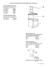
1” min
16
3/8” max
22”
9
1/2”
36”
x
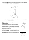
also consult cooktop
manufacturer's recommendation
upper
chimney
lower
chimney
canopy
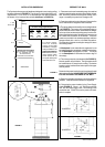
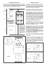
x = distance from hood to cooktop
(varies depending on installation)
min - 24”, suggested max - 30”
cabinet base
FIGURE 4
19 1/4”
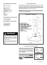
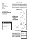
PREPARE THE WALL
1. Disconnect and move freestanding range from cabinet
opening to provide easier access to upper cabinet and rear
wall. Put a thick, protective covering over cooktop, set-in
range or countertop to protect from damage or dirt.
2. Determine and clearly mark with a pencil the center line
on the wall where the rangehood will be installed.
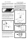
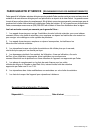
3. The canopy attaches to the wall by two mounting brackets
(1 in FIGURE 5). The canopy of the rangehood hangs on
the two brackets which must be mounted with the anges
on the top of the bracket and pointing away from the wall.
Before installing the brackets, the adjustment screws must
be installed into the bottom of the bracket. These two
screws are provided in the hardware package and have
hexagon heads with a slot for a at blade screwdriver.
The dimensions illustrate mounting the canopy 24" above
the cooking surface.
If a Backsplash is to be used with this rangehood, it must
be installed before the rangehood. Installation instructions
for the Backsplash are supplied in its box. The height
of the Backsplash will determine the bottom edge of
the canopy.
4. The chimney mounts by two brackets (2 in FIGURE 5).
Note the position of the brackets. The top bracket should
be installed about 1/8" away from the ceiling. The bottom
bracket must be installed at the bottom point of the upper
chimney sleeve.
Determine the proper location for each bracket and install
the brackets on the wall. MAKE SURE THAT THE BRACK-
ETS ARE SECURELY FASTENED TO THE WALL.
5. Determine and make all necessary cuts in the wall for the
ductwork. Install the ductwork before the rangehood.
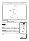
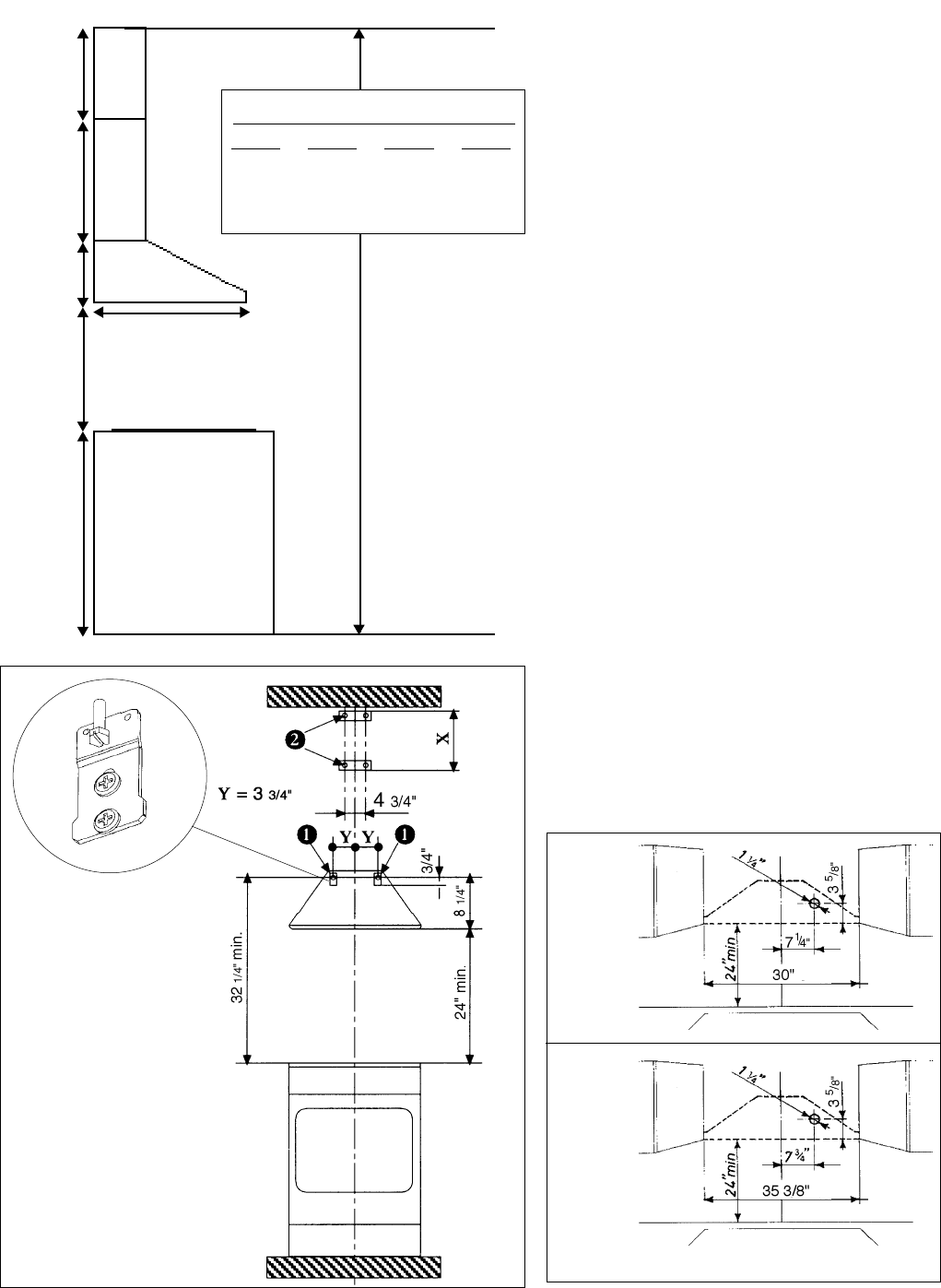
6. Determine the proper location for the Power Supply
Cable (FIGURE 6). Use a 1 1/4" Drill Bit to make this
hole. Run the Power Supply Cable. Use caulking to seal
around the hole. DO NOT turn on the power until instal-
lation is complete.
INSTALLATION DIMENSIONS
The Synthesis chimneys are adjustable and designed to meet varying ceiling
heights as indicated in FIGURE 4. The chimneys can be adjusted for ceil-
ings between 7' 8 1/2" and 9' 5 7/8" depending on the distance between
the bottom of the hood and the cooktop (distance x in FIGURE 4).
FIGURE 5
FIGURE 6
30 MODELS
36 MODELS
For shorter ceilings,
have the chimney
cover(s) cut at a sheet
metal shop. For higher
ceiling installations, the
High Ceiling Chimney
Kit includes a new 40”
upper chimney which
would replace the 16
3/8” upper chimney that
came with the hood.
min & max ceiling height examples
x = 30"
min
8'
2 1/2"
max
9'
5 7/8"
x = 28"
min
8'
1/2"
max
9'
3 7/8"
x = 26"
min
7'
10 1/2"
max
9'
1 7/8"
x = 24"
min
7'
8 1/2"
max
8'
11 7/8"