


Version 04/08 - Page 7
.
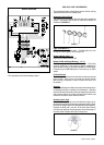
ATTACH THE SUPPORT
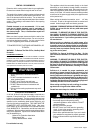
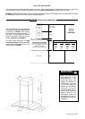
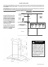
4. Determine and make necessary cuts for the ductwork. The duct
opening is shown on the mounting template (L in FIGURE 6). Install
ductwork before mounting the support.
FIGURE 8
FIGURE 6
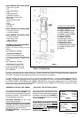
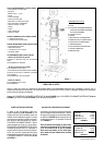
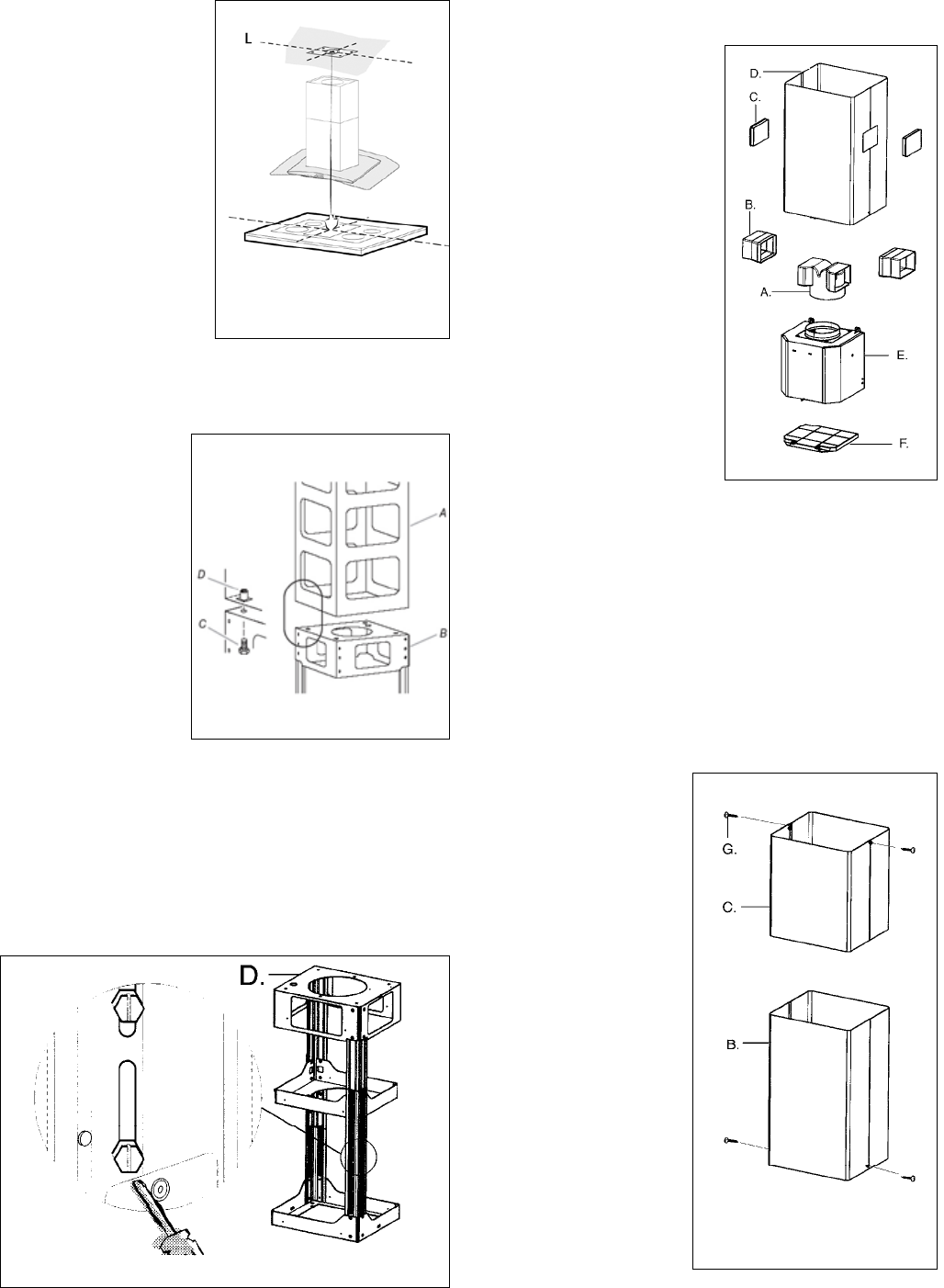
Ductless installations require
a Ductless Conversion
Kit whose components are
pictured in FIGURE 9. Do
not use the DAMPER (M
in FIGURE 1) for ductless
installations. The LOWER
CHIMNEY COVER (B
in FIGURE 1) should be
discarded and replaced by
the new one with holes from
the Ductless Conversion Kit
(D in FIGURE 9).
As indicated in FIGURE
9, place the DUCTLESS
DIVERTER (A) over the
exhaust opening of the EASY
CUBE (E). Fit the DUCTLESS
DIVERTER EXTENSIONS
(B) into the
DIVERTER (A).
FIGURE 9
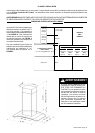
FIGURE 10
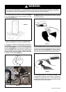
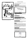
MAKE THE ELECTRICAL CONNECTION
DO NOT
turn on the power until installation is complete! Connect
the Power Supply Cable to the rangehood. Connect the Green
(Green and Yellow) ground wire under the Green grounding
screw. Attach the White lead of the power supply to the White
lead of the rangehood with a twist-on type wire connector.
Attach the Black lead of the power supply to the Black lead of
the rangehood with a twist-on type wire connector.
1. Put a thick, protective
covering over cooktop,
set-in range or countertop
to protect from damage
or dirt.
2. Determine and clearly
mark with a pencil on the
ceiling where the rangehood
will be installed.
3. A template (L in FIGURE
6) for mounting the support
is supplied in the carton
with the support. Use this
template to mark holes for
support on the ceiling.
FOR DUCTLESS INSTALLATIONS
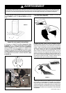
1. The UPPER CHIMNEY
COVER (C in FIGURE 10)
attaches using two screws
provided (G in FIGURE 10).
If using the High Ceiling
Chimney Kit, use the
UPPER CHIMNEY COVER
supplied with the kit. Slide
up and attach the UPPER
CHIMNEY COVER.
2. Attach the duct work to the
DAMPER (M in FIGURE 1).
Make sure to seal all joints
with duct tape to prevent
leaks.
3. The LOWER CHIMNEY
COVER (B in FIGURE
10) attaches using two
screws provided (G in
FIGURE 10). Install the
LOWER CHIMNEY COVER
For ductless installations, line up the DUCTLESS DIVERTER
(B in FIGURE 9) with the holes
in the LOWER CHIMNEY COVER (D in FIGURE 9) and snap
in the VENT GRIDS (C in FIGURE 9).
INSTALLING THE RANGEHOOD
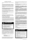
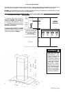
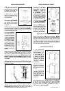
8. Attach the CHIMNEY SUPPORT (D in FIGURE 8) to the ceiling.
the desired length of the support structure and adjust the length of the
support by removing the four screws (indicated in FIGURE 8) with a
install and tighten the four screws.
6. Determine the proper location for the Power Supply Cable as
indicated on the template. Use a 1 1/4" Drill Bit to make this hole. Run
the Power Supply Cable. Use caulking to seal around the hole. DO
NOT turn on the power until installation is complete! A knockout is
provided at the top of the CHIMNEY SUPPORT (D in FIGURE 8).
7. For ducted installations, place the round DAMPER (N in FIGURE
1) into the exhaust opening of the rangehood and press down.
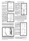
5. If using the High Ceiling
Chimney Kit, remove
the CHIMNEY COVER
from the CHIMNEY
EXTENSION (A in
FIGURE 7). Position the
CHIMNEY EXTENSION
over the CHIMNEY
SUPPORT (B in FIGURE
7) so that the outside
edges and the electrical
holes line up. Attach the
CHIMNEY EXTENSION to
the CHIMNEY SUPPORT
using the 4 bolts (C in
FIGURE 7). Tighten bolts
securely.
FIGURE 7