


Version 04/08 - Page 8
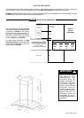
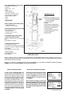
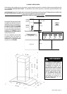
For ductless installations, install the CHARCOAL FILTER (F in
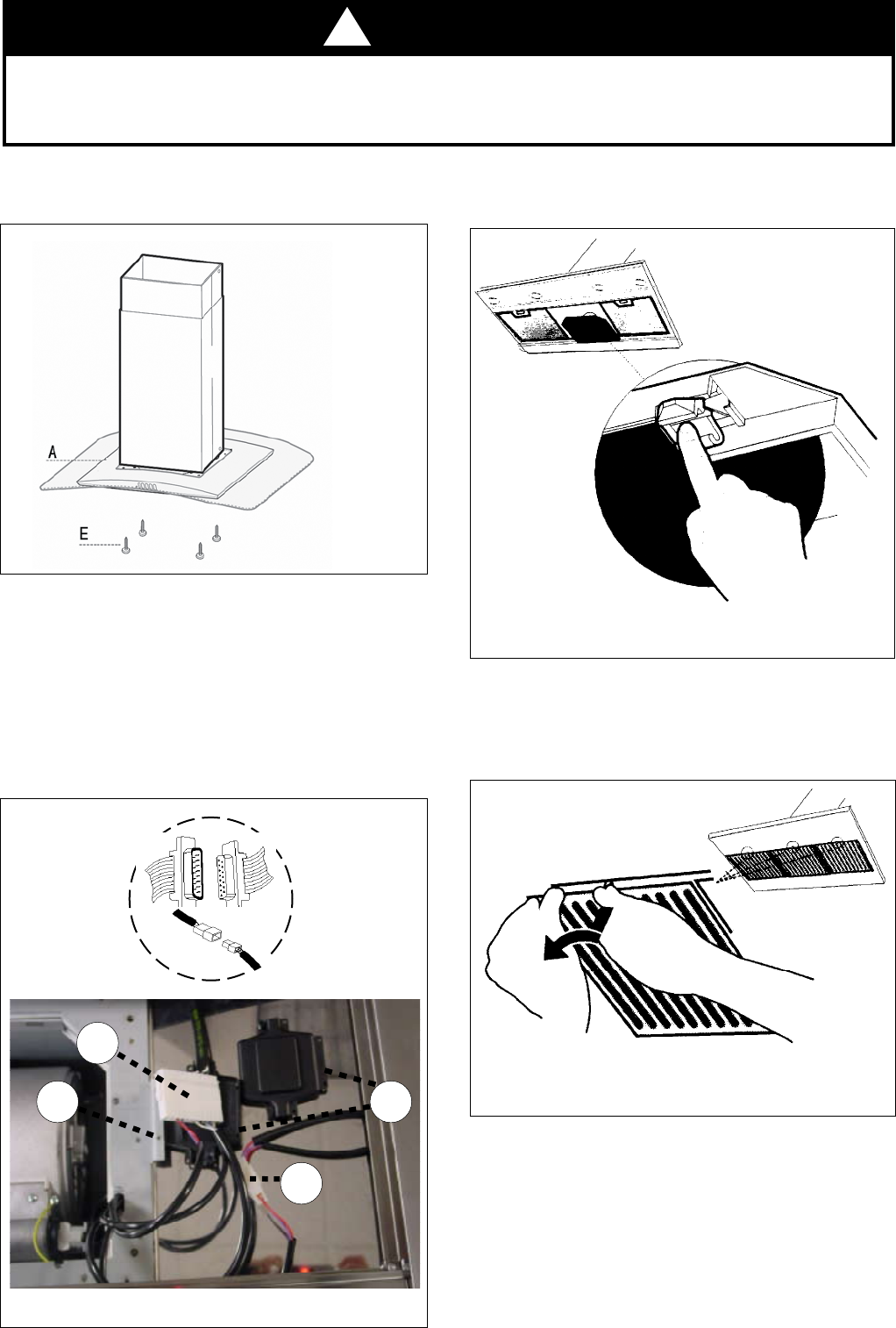
FIGURE 9)
and locking into place.
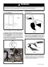
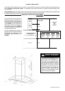
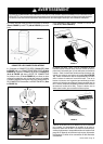
WARNING
Two people must hold the canopy in place while the third person installs the screws that attach the canopy to the chimney.
The manufacturer assumes no responsibility for injury or damage caused by improper installations.
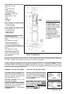
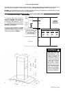
4. From below, attach the CANOPY SECTION (A in FIGURE
11) to the assembled chimney support using the four bolts
provided (E in FIGURE 11).
FIGURE 11
FIGURE 13
6.
turning the knob to the left so that the locking lever does not
(as in FIGURE 14). Insert the opposite
FIGURE 14
7. Turn the power supply on. Turn on blower and lights. If the
rangehood does not operate, check that the circuit breaker is
not tripped or the house fuse blown. If the unit still does not
operate, disconnect the power supply and check that the wiring
connections have been made properly.
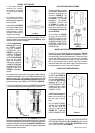
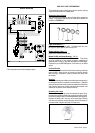
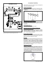
5. Connect the CONTROL CABLES together as indicated in
A in FIGURE 12. Connect the LIGHT CABLES together as
indicated in B in FIGURE 12. Insert the connected CONTROL
CABLES (A in FIGURE 12) into the black plastic CONNECTOR
BOX (C in FIGURE 12) by connecting the two black plastic
pieces using the four screws provided. Using the two longer
screws provided, attach the assembled CONNECTOR BOX to
the METAL FLANGE (D in FIGURE 12).
FIGURE 12
MAKE THE INTERNAL ELECTRICAL CONNECTIONS
C
A
B
D
A
B
!