


Version 03/08 - Page 7
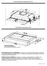
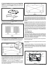
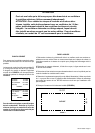
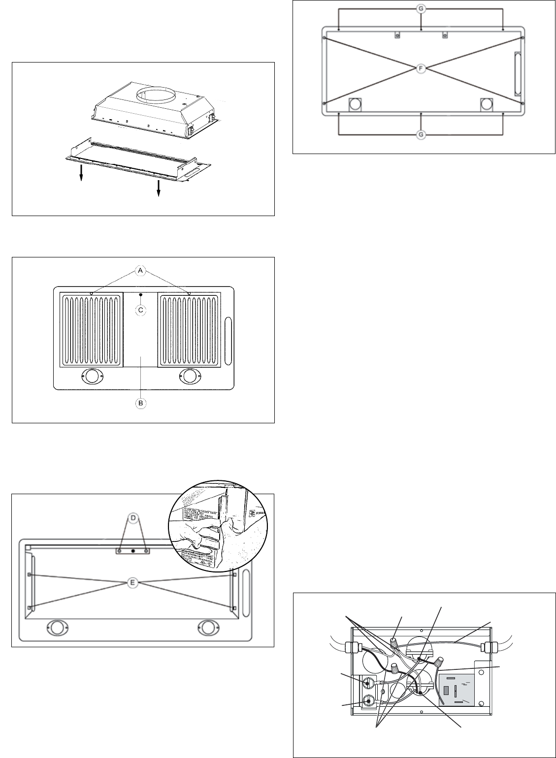
4. Remove the two philips screws (D in FIGURE 8). Remove the entire
bottom of the rangehood by pushing your thumb into the side holes
(E in FIGURE 8) and pulling the sides free from the rangehood.
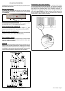
FIGURE 6
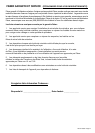
FIGURE 7
FIGURE 8
3. Remove the grease lter divider (B in FIGURE 7) by rst removing
the plastic screw cover (C in FIGURE 7), then removing the phillips
screw under the screw cover.
7. If the optional remote wall control switch is being used, please
follow the instructions included with the remote wall switch pack-
age. After following those instructions, skip to step #9 below. If the
optional wall control switch is not being used, continue to step
#8 below.
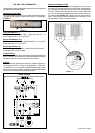
8. Remove the wiring box cover by removing the two screws. (See
FIGURE 10 for reference) Insert the cable of the remote blower into
the knockout hole of the rangehood. Insert the power supply cable
into the hole of the rangehood. Connect the green ground wire from
the power supply to the ground screw. Connect the green ground
wire from the remote blower to the other green ground screw. Con-
nect the black remote blower motor wire to the brown rangehood
wire with a twist-on wire connector. Next connect together with a
twist-on wire connector the following wires: - white remote blower
motor wire
- white rangehood wire
- violet rangehood wire
- 120-volt white supply wire
Connect the black power supply wire to the black rangehood wire
with a twist-on connector. Replace the wiring box cover. Tighten the
screw securely. Reinstall the bafe lters. Reconnect the power.
Twist on wire connectors should be suitable for connecting
multiple wires of different sizes together.
9. Replace the bottom of the rangehood and reinsert the grease lter
divider and grease lters.
10. Connect the ductwork to the rangehood and seal all connections
with duct tape.
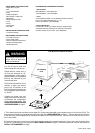
11. Turn the power supply on. Turn on the blower and light. If the
rangehood does not operate, check that the circuit breaker is not
tripped or the house fuse blown. If the unit still does not operate,
disconnect the power supply and check that the wiring connections
have been made properly.
FIGURE 9
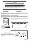
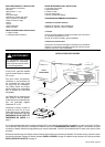
2. The entire bottom of the rangehood must be removed for installation
as indicated in FIGURE 6. Remove the grease lters USING TWO
HANDS (one to hold the lter so that it doesn't fall on cooktop and
one to turn the knob (A in FIGURE 7) by pulling the knob out and
turning to the left.
FIGURE 10
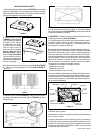
5. Fix the rangehood to the cabinet or custom hood using the four
spring loaded brackets, two on each side of the rangehood. Using
a philips screwdriver or drill, tighten the adjustment screws (F in
FIGURE 9) until the brackets adhere tightly to the surface.
6. IMPORTANT: There are 6 holes (G in FIGURE 9) for screws
(not provided) to reinforce the rangehood to your cabinet or custom
hood. Use screws appropriate for the size and type of materials of
your cabinet or custom hood.