


Version 7/07 - Page 7
X X
X X
X X
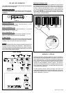
F
G
G
G
G
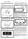
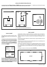
D
X X
E
A
C
C
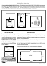
B
INSTALL THE RANGEHOOD
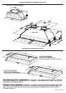
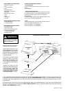
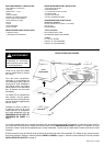
1. Remove the rangehood from the carton and place on a at sur-
face. Cover the surface to prevent accidental damage. Remove all
parts including the backdraft dampers and literature package before
discarding the carton.
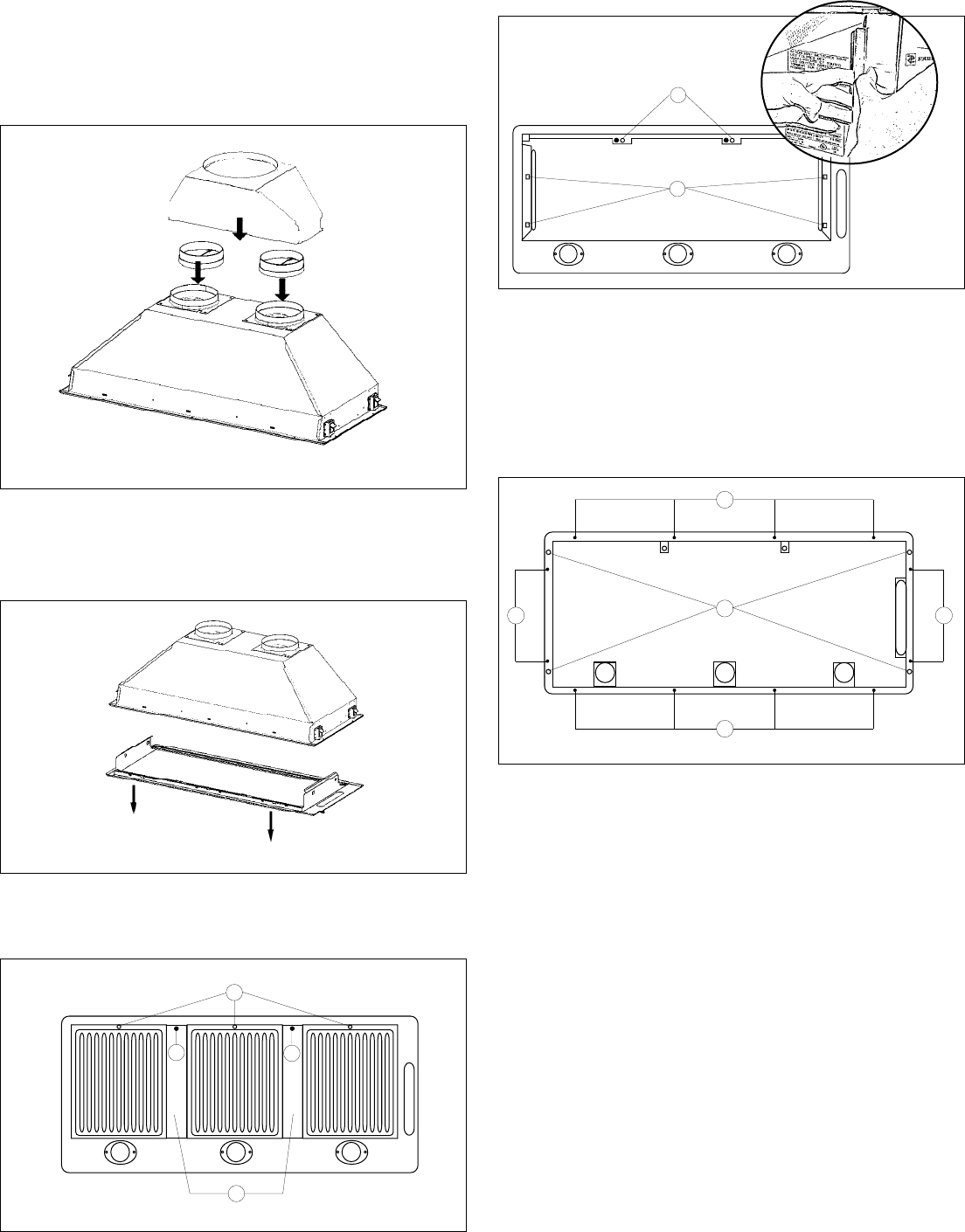
2. Place the round dampers into the exhaust openings of the range-
hood and press down as indicated in FIGURE 5. If using optional
Duct Transition Kit, t this over the two round dampers and screw
onto the top of the unit (screws not provided). Use duct tape to secure
if necessary.
5. Remove the two philips screws (D in FIGURE 8). Remove the entire
bottom of the rangehood by pushing your thumb into the side holes
(E in FIGURE 8) and pulling the sides free from the rangehood.
FIGURE 6
FIGURE 7
6. Fix the rangehood to the cabinet or custom hood using the four
spring loaded brackets, two on each side of the rangehood. Using
a philips screwdriver or drill, tighten the adjustment screws (F in
FIGURE 9) until the brackets adhere tightly to the surface.
7. IMPORTANT: There are 12 holes (G in FIGURE 9) for screws
(not provided) to reinforce the rangehood to your cabinet or custom
hood. Use screws appropriate for the size and type of materials of
your cabinet or custom hood.
FIGURE 8
4. Remove the grease lter dividers (B in FIGURE 7) by rst removing
the plastic screw cover (C in FIGURE 7), then removing the phillips
screw under the screw cover.
8. Replace the bottom of the rangehood and reinsert the grease lter
dividers and grease lters.
9. Remove the cover from the eld wiring compartment with a phillips
screwdriver. Feed the Power Supply Cable through the electrical
knockout. Connect the Power Supply Cable to the rangehood cable.
Attach the White lead of the power supply to the White lead of the
rangehood with a twist-on type wire connector. Attach the Black lead
of the power supply to the Black lead of the rangehood with a twist-on
type wire connector. Attach the Power Supply Cable grounding lead to
the green screw provided. Using the 4 holes provided screw the eld
wiring compartment to the wall or cabinet as dictated by your Power
Supply Cable location (screws not provided). Replace the cover.
10. Connect the ductwork to the dampers or Duct Transition Kit and
seal all connections with duct tape.
11. Turn the power supply on. Turn on the blower and light. If the
rangehood does not operate, check that the circuit breaker is not
tripped or the house fuse blown. If the unit still does not operate,
disconnect the power supply and check that the wiring connections
have been made properly.
FIGURE 9
3. The entire bottom of the rangehood must be removed for installation
as indicated in FIGURE 6. Remove the grease lters USING TWO
HANDS (one to hold the lter so that it doesn't fall on cooktop and
one to turn the knob (A in FIGURE 7) by pulling the knob out and
turning to the left.
FIGURE 5