


Version 09/05 - Page 5
4. Determine and make all necessary cuts for the ductwork.
Install damper when connecting ductwork. Install ductwork
before mounting the support. The damper attaches to the
inside bottom of the chimney support structure. It is necessary
to attach your ductwork to this damper and run the ductwork
inside the chimney support structure.
5. Determine the proper location for the Power Supply
Cable as indicated on the template. Use a 1 1/4" Drill Bit to
make this hole. Run the Power Supply Cable. Use caulking
to seal around the hole. DO NOT turn on the power until
installation is complete! Two knockouts are provided near
the exhaust exit on the canopy. One is for the Power Supply
Cable and one for an optional remote blower. Make sure that
you use the correct knockout.
6. Attach the support to the ceiling. Make sure that the
support is firmly connected to the ceiling. The height of
the canopy can be adjusted by changing the length of the
support.
ATTACH THE SUPPORT
1. Put a thick, protective covering over cooktop, set-in
range or countertop to protect from damage or dirt.
2. Determine and clearly mark with a pencil the center on
the ceiling where the rangehood will be installed.
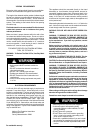
FIGURE 5
FIGURE 6
INSTALL THE RANGEHOOD
1. Remove the unit from the carton and place on a flat
surface for assembly. Cover the surface to prevent accidental
damage. Remove all parts including the mounting hardware
before discarding the carton.
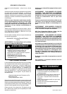
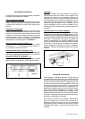
FIGURE 7
3. Remove the cover from the field wiring compartment.
Remove the wiring electrical knockout using a flat-blade
screwdriver.
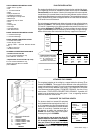
FIGURE 8
5. Lift the canopy and insert the bolts into the slots on
the support. Tighten the four bolts. Due to the weight of the
rangehood, two people should lift it to avoid injuries. Make
sure that the bolts are properly seated in the slots and fully
tightened.
6. Connect the Power Supply Cable to the rangehood.
Attach the White lead of the power supply to the White lead
of the rangehood with a twist-on type wire connector. Attach
the Black lead of the power supply to the Black lead of the
rangehood with a twist-on type wire connector. Connect the
Green ( Green and Yellow ) ground wire under the Green
grounding screw.
If your installation uses an optional remote blower, connect
the wiring cable for the blower. DO NOT CONNECT THE
REMOTE BLOWER DIRECTLY TO THE POWER SUPPLY
CABLE IN THE FIELD WIRING COMPARTMENT.
7. Replace the wiring compartment cover and grease
filters.
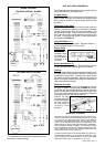
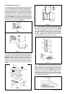
4. The canopy attaches
to the support by four bolts
located next to the duct
exhaust opening. Loosen
the four bolts so that there
is approximately 1/4" space
between the bolt head and
the canopy. FIGURE 8 shows
how the canopy attaches to
the support.
2. Remove the grease
filters and set aside. The
grease filters are removed by
pressing the handle in front
of the filter as indicated in
FIGURE 7. When replacing,
make sure the filters are
properly positioned with the
handles visible in front.
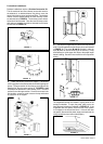
Adjust the support length
by loosening the four set
screws (V in FIGURE 6).
The bottom of the canopy
will be approximately 10 1/4
inches below the bottom of the
support. Make sure that all four
set screws are firmly tightened
before attaching the canopy. To
prevent damage, the support
must be adjusted BEFORE
attaching the canopy.
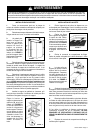
WARNING
DUE TO THE SIZE AND WEIGHT OF THIS RANGEHOOD, THE SUPPORT MUST BE FIRMLY ATTACHED TO THE
CEILING. For plaster or sheet rock ceilings, the support must be attached to the joists. If this is not possible, a support
structure must be built behind the plaster or sheet rock. The manufacturer assumes no responsibility for injury or damage
caused by improper installations.
3. A tem plate for
mounting the support is
supplied in the carton
with the support. Use
this template to mark
holes for support on the
ceiling. The chimney
must be disassembled
as indicated in FIGURE
5 to reveal the support.
Before disassembling
the chimney, remove all
screws ( 3 ).
!